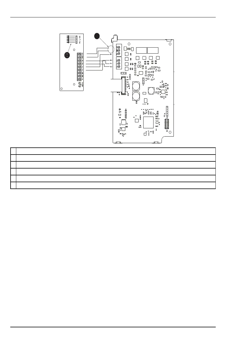
PCL-422
Mounted in Alarm Controller Cabinet
HSPA Controller Board
RX-
RX+
TX+
TX-
+12V
GND
+12V
GND
E
F
A Red wire on alarm controller PCLink2 Header
B Antenna access ports
C Ethernet cable connection
D Quad cables (100' / 30m maximum)
E Red wire on PCL-422 PCLink Header
F HSPA Controller Board power terminals. Can be connected to power supply module (HSM2204/2300).
Step 1: Enable module
For the Alarm.com module to communicate with the panel, section [382] option 5 at the panel must be set to
ON. This section is OFF by default and must be enabled for the system to function properly. This should be
done before connecting the PC-Link cable to power up the module to ensure all initialization commands are
processed properly.
Step 2: Connect the TL8803GI-EU
Caution: Ensure that the alarm panel is fully powered down (i.e., AC and battery disconnected) prior to con-
necting the TL8803GI-EU.
1: Connect data bus
The maximum cable length permitted for the data bus is 100ft/30m.
l Connect the RX+ terminal on the TL8803GI-EU to the TX+ terminal on the PCL-422
l Connect the RX- terminal on the TL8803GI-EU to the TX- terminal on the PCL-422
l Connect the TX- terminal on the TL8803GI-EU to the RX- terminal on the PCL-422
l Connect the TX+ terminal on the TL8803GI-EU to the RX+ terminal on the PCL-422
- 9 -
Installation