15
1-3/4" (45mm)
3/4" (19mm)
5.6 Coaxial Venting Instructions
Coaxial Pipe Vent Lengths
Boiler Size 125/150
Vent Size
4"/2"
[100 mm/50 mm]
Maximum Minimum
Natalini 32.80 ft [10 m]
6 ft
[1.8m]
DuraVent
®
27.88 ft [8.5 m]
Centrotherm 24.60 ft [7.5 m]
Coaxial Elbows - Equivalent length
4"/2" [100 mm/60 mm]
45°
1.64 ft. [0.5 m]
90°
3.28 ft. [1.0 m]
NOTE: Coaxial venting can run horizontal or vertical.
•
elbow to desired orientation (rear, right or left).
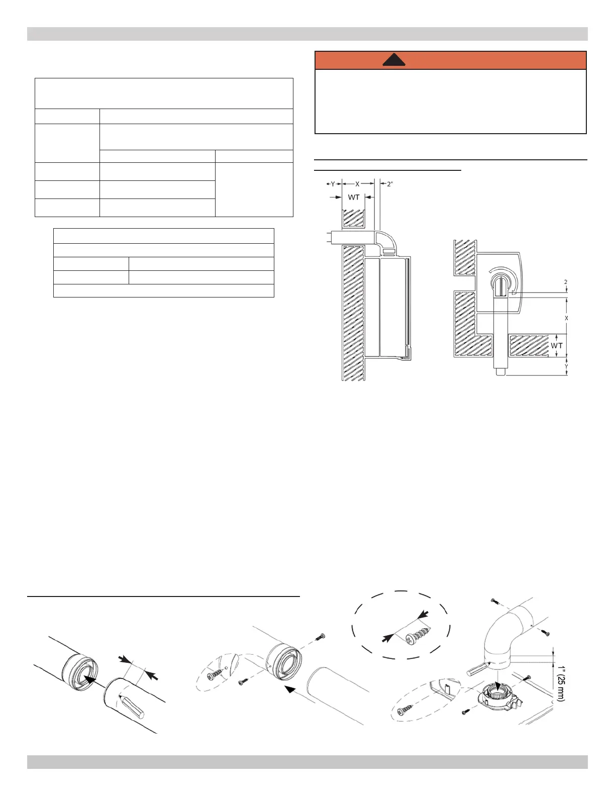
• Measure distance from outside wall face to elbow, this
dimension will be known as 'X", add distance "Y" + 2" (50
mm) to "X" this is the total dimension of the vents. See
Figure 5-4.
• Mark dimension from above on outer aluminum intake
vent. Measure length of waste material, and transfer
•
intake air vent and pass them through hole in wall.
• Check all measurements before cutting. Clearance to
combustible materials is zero when using coaxial vent
system.
• After installing venting use calibrated analyzer to verify
there is no recirculation of combustion.
• Ensure termination is positioned with slots at the bottom.
Figure 5-2 - Coaxial Screw Placement
5.7 Coaxial Vent Screw Placement - See Figure 5-2
Two (2) screws shall be fastened through the outer intake pipe
apart. Note the screws used must be no larger than No. 8-3/4
sheet metal screws and must be zinc coated.
WARNING
Asphyxiation hazard. Before securing the screws
ensure the pipe has been pushed in a minimum of
1-3/4" (45 mm) into the gasket end of the other pipe.
Failure to follow these instructions could result in
death or serious injury.
!
WT = Wall Thickness
(2" is insertion depth of straight pipe to elbow)
FIGURE 5-3 - Coaxial Venting Horizontal or Vertical
CAN BE USED ON ALL SIZES
5 - COMBUSTION AIR AND VENT PIPING
240012564 REV A, [05/15/2019]


 To Next Page