25
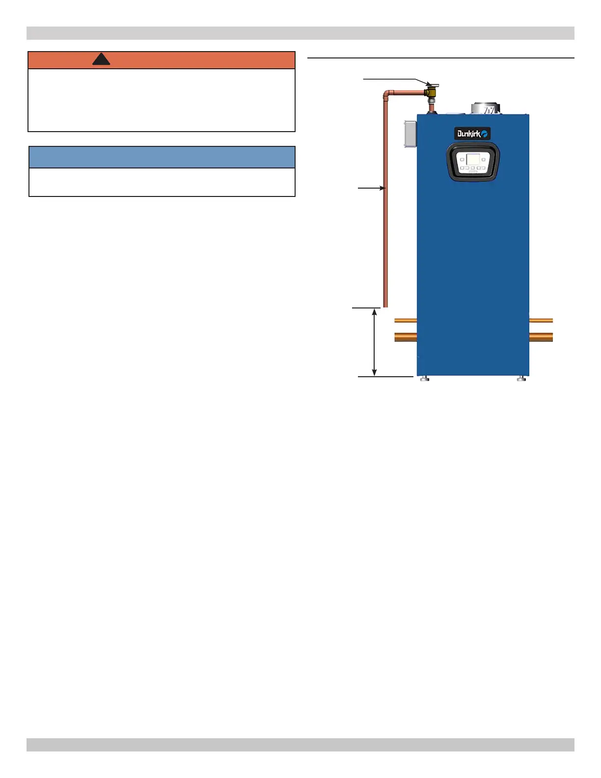
6.3 Safety Relief Valve and Air Vent
•
with boiler. See Figure 6-1.
• Install safety relief valve with spindle in vertical
position.
•
relief valve.
• Install discharge piping from safety relief valve. Do not
use plastic pipe.
• Use ¾" or larger pipe.
• Use pipe suitable for temperatures of 375°F (191°C) or
greater. Do not use plastic pipe on safety relief valve.
• Individual boiler discharge piping shall be independent
of other discharge piping.
• Size and arrange discharge piping to avoid reducing
safety relief valve relieving capacity below minimum
relief valve capacity stated on rating plate.
• Run pipe as short and straight as possible to location
protecting user from scalding and properly drain piping.
• Install union, if used, close to safety relief valve outlet.
• Install elbow(s), if used, close to safety relief valve
outlet and downstream of union (if used).
• Terminate pipe with plain end (not threaded).
Check Local
Codes For
Maximum
Distance To Floor
Safety Relief
Valve
Do not use
plastic pipe see
Warning above.
WARNING
Burn and scald hazard. Safety relief valve could
discharge steam or hot water during operation.
Use pipe suitable for temperatures of 375°F (191°C)
or greater. DO NOT use plastic pipe. Install discharge
piping per these instructions.
!
6 - HYDRONIC PIPING
FIGURE 6-1 Safety Relief Valve
6.4 Trim Piping
• Temperature - Pressure Gauge. Install temperature
pressure gauge in near boiler piping on supply side.
• Some boiler models may have integral drain valve located
inside jacket directly underneath pump. Install external
NOTICE
When installing safety relief valve it must be installed
in a vertical position with spindle at top.
6.5 System Piping
•
•
prevention device.
• Single boiler system. See Figures 6-5, 6-6,
for general
guidance. Additional considerations:
• Boiler control only supports integrated pump. Installer
responsible for integration of multiple central heating
• Boiler control allows domestic hot water
prioritization.
•
•
•
Follow local code with respect to necessary distance to the
See Figure 6-1.
• Verify all drain valves are closed.
240012564 REV A, [05/15/2019]

 Loading...