34
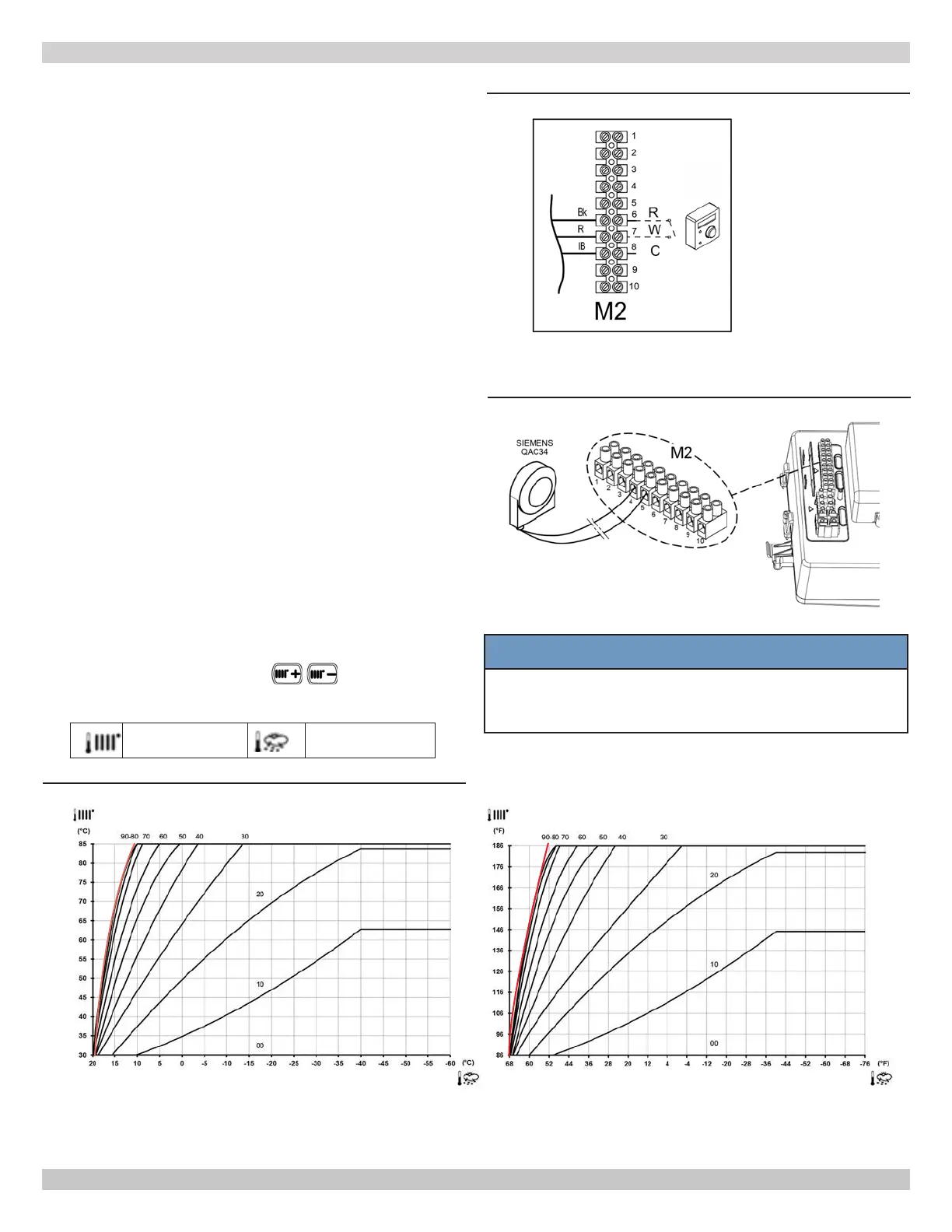
A. Connect Room End Switch
•
• access terminal block M2;
• connect room end switch to terminals 6(R)-7(W)-
8(C); Do not apply dry volt between 2 terminals. Dry
contact only.
• turn boiler power on;
• verify room end switch operates per end switch
manufacturer's instructions.
NOTE: maximum load allowed is 10 mA
Dry contact end switches from various manufacturers can be
attached to boiler control PCB.
FIGURE 8-4 Thermostat Connections
8.6 Install Room End Switch
Install room end switch on inside wall. Do not install where it
Dry contact only - do not apply 24 volts between 6 and 7.
A
Room
End Switch
8 - ELECTRICAL CONNECTIONS
8.7 Optional Electrical Connections
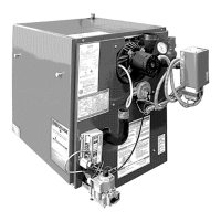
A. 1K Ohm (1K Ω) Outdoor Temperature Sensor
instructions supplied with
1K Ω sensor.
B. Setting "Kt" Climate Curve
When external
1K Ω sensor is connected to boiler, the
as indicated in
chart below for selecting the appropriate curve (00 to 90).
Flow temp Outside temp
FIGURE 8-5 Outdoor Sensor Connections
NOTE:
on graph become horizontal.
Boiler setpoint will override sensor setpoint.
FIGURE 8-6 Kt Climate Curves
80 Is Default.
1K Ω
NOTICE
Sensors used for this boiler are proprietary to the
manufacturer. Use of after market sensors will diminish
boiler performance.
240012564 REV A, [05/15/2019]