27
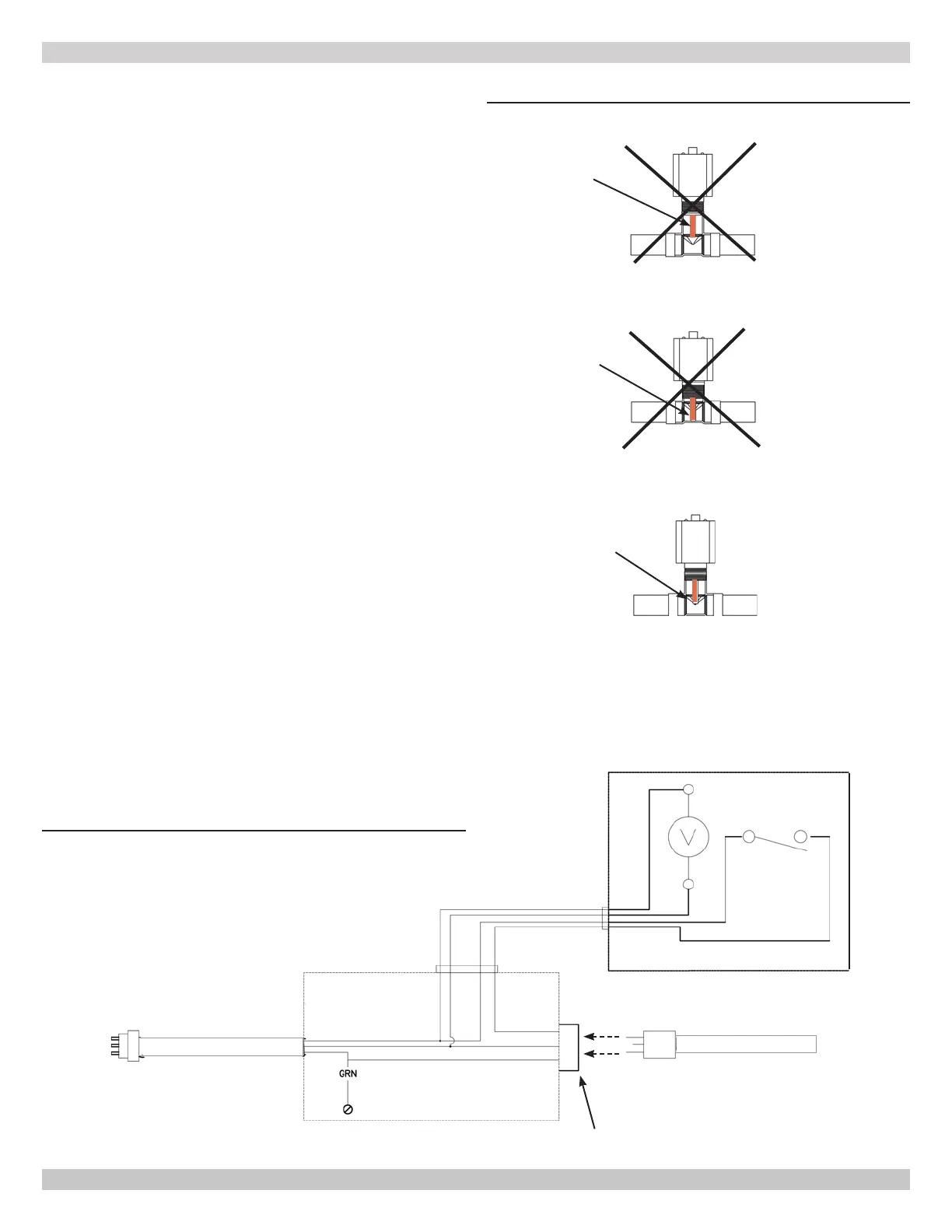
NO
NO
YES
FIGURE 6-3 - Low Water Cuto - Detail
6.6 External Optional Low Water Cut O
These guidelines are supplied when necessary to install an
Jurisdiction.
Follow LWCO manufacturer installation instructions for type of
LWCO selected in addition to these instructions.
LWCO shall be 120V/60HZ control and dry contacts sized for
load being connected. Wire control to boiler. See Figure 6-4.
Connect LWCO device to the system ground. Ground in
National Electrical Code (NEC) or Canadian Electrical Code
CEC.
• Locate LWCO sensing device in the supply
piping, above the minimum height of boiler.
See Figure 6-2, Piping Diagram.
• Position control in HORIZONTAL piping to assure proper
boiler protection (upright or 90° rotation).
• For proper operation, sensing element of the LWCO
control shall be positioned in the tee to sense the main
walls. Element shall NOT contact the rear, or side walls of
the tee. See Figure 6-3.
• Install an air vent using a tee to avoid nuisance
shutdowns.
• Apply small amount of pipe sealant to threaded
connections.
• Arrange piping to prevent water dripping onto boiler.
•
LWCO sensing device.
Electrical Conduit
J-Box
120 V/60 HZ
Conduit or Power
Supply cord
(Polarized)
L
1
N
G
GND
L
1
N
GND
BLK
WHT
120 V/60 HZ Socket
(Polarized) 120 V/60 HZ
Cord Set From Boiler
N.O
FIGURE 6-4 - LWCO Wiring Diagram
6 - HYDRONIC PIPING
240012564 REV A, [05/15/2019]


 To Next Page