11 | Appendix: Plans and drawings
100
D-LX 201/721
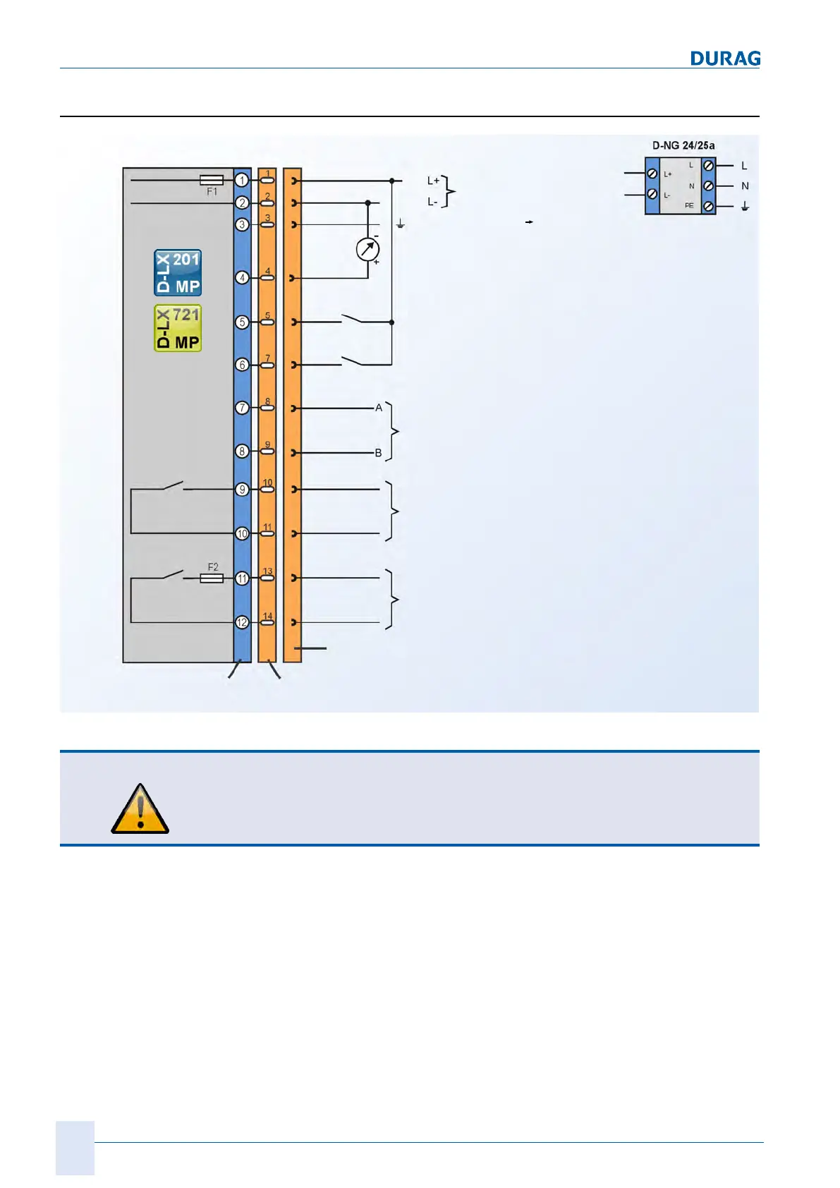
11.2 Connection diagram for D-LX 201/721 MP
Red
Blue
Grey
Pink
Green/yellow
Ready for operation
Yellow
Flame ON
Green
White
Brown
DC network
AC power supply
(accessories)
Functional earth (FE)
Terminal strips
Fieldbus: RS485/Modbus RTU
Range switching
External reset
Analogue output (0/4 ... 20 mA)
Orange
Black
Violet
Cable jack
MP 3 panel plug (on
flame monitor)
Protective
earth
Fig.11.2: Connection diagram for D-LX 201/721 MP
CAUTION
At the "ready for operation" contact output, only non-reactive components such as
relay or contactor coils may be operated via an external fuse
This measure provides protection against contact welding in accordance with EN298.