8 | Flame monitor settings
72
D-LX 201/721
The switches described below are produced separately for each channel, i.e. are
provided in duplicate (hereinafter referred to as channel 1 and channel 2). This en-
sures that the self tests will also detect any misconduct or switch defects, and will trig-
ger an error shutdown. If the setting is changed, both switches must be flipped (simul-
taneously within 8 secs) and moved into the same position.
The flame monitor has switching thresholds for the intensity (Intens.) and the flicker
frequency of the flame. You set the threshold for the intensity with rotary switches (see
section 8.2 Setting the threshold for the intensity [}73]); you set the threshold for the
flicker frequency of the flame with a DIP switch [}115] (see section 8.4 Setting the
threshold for the flicker frequency [}77]).
Different gain characteristic curves can be selected via rotary switches in order to ad-
apt the flame monitor to the local combustion conditions. The amplification of the
flame signal can be selected such that the flame monitor can clearly differentiate
between flame ON and flame OFF by means of the intensity switching threshold (see
section 8.3 Selecting the gain characteristic curve [}75]).
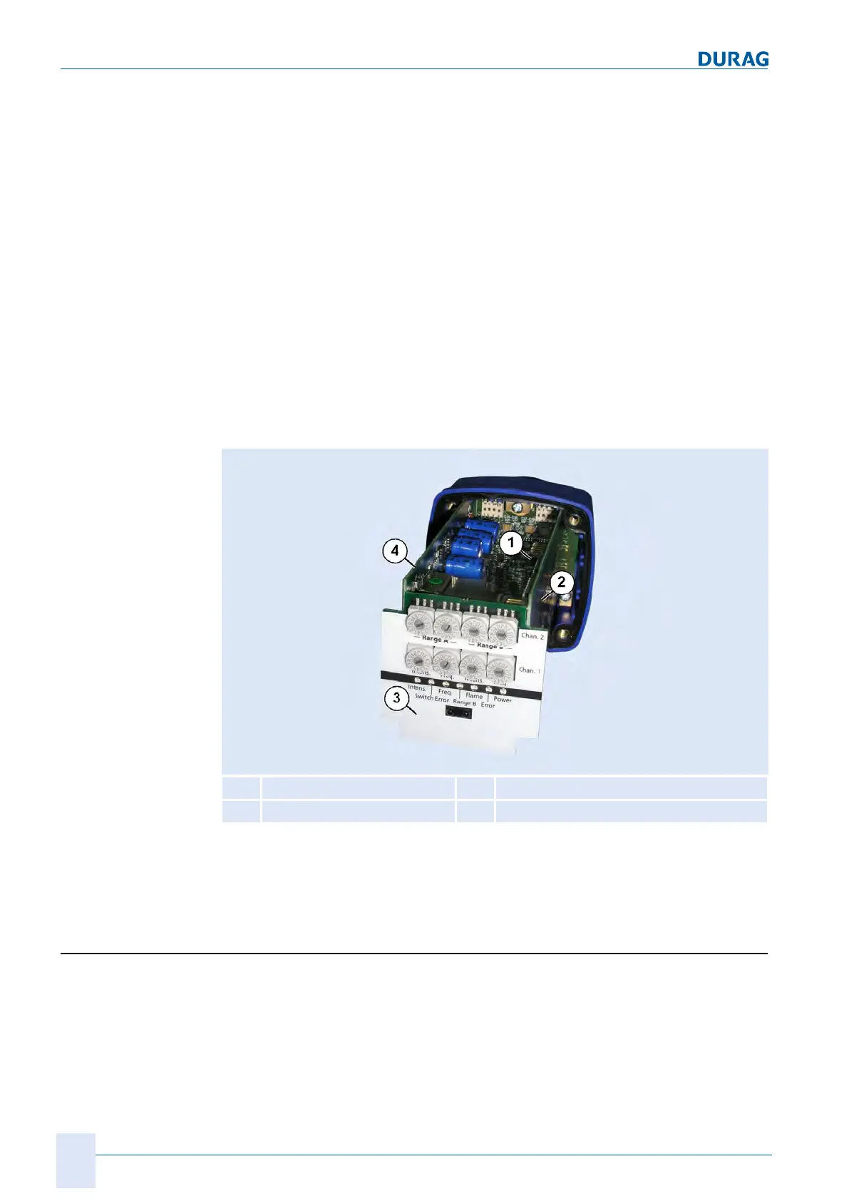
The switches for the intensity (Intens.) and for selecting the gain characteristic curves
can be found on printed circuit board no. 6, and the DIP switches for selecting the
flicker frequency of the flame are located on printed circuit board no. 2. The names of
the printed circuit boards can be seen in the following figure:
1
Printed circuit board no. 1
3
Printed circuit board no. (front panel)
2
Printed circuit board no. 2
4
Printed circuit board no. 4
Fig.8.1: Printed circuit board numbering
Also see about this
2 [}117]
8.1 Range selection
The purpose of the range switching is to use suitable settings for two different burner
operating states (e.g. gas and oil operation, start-up and full load etc.) that allow for
the most effective detection of the flame signal. Relevant settings are the switching
thresholds for intensity and flicker frequency, the gain characteristic curves and the
FFDT.
If the ranges (range A and range B) are used for different firing states, different gain
characteristic curves may prove optimal for the different ranges.