6 | Configuration and function
D-LX 201/721
49
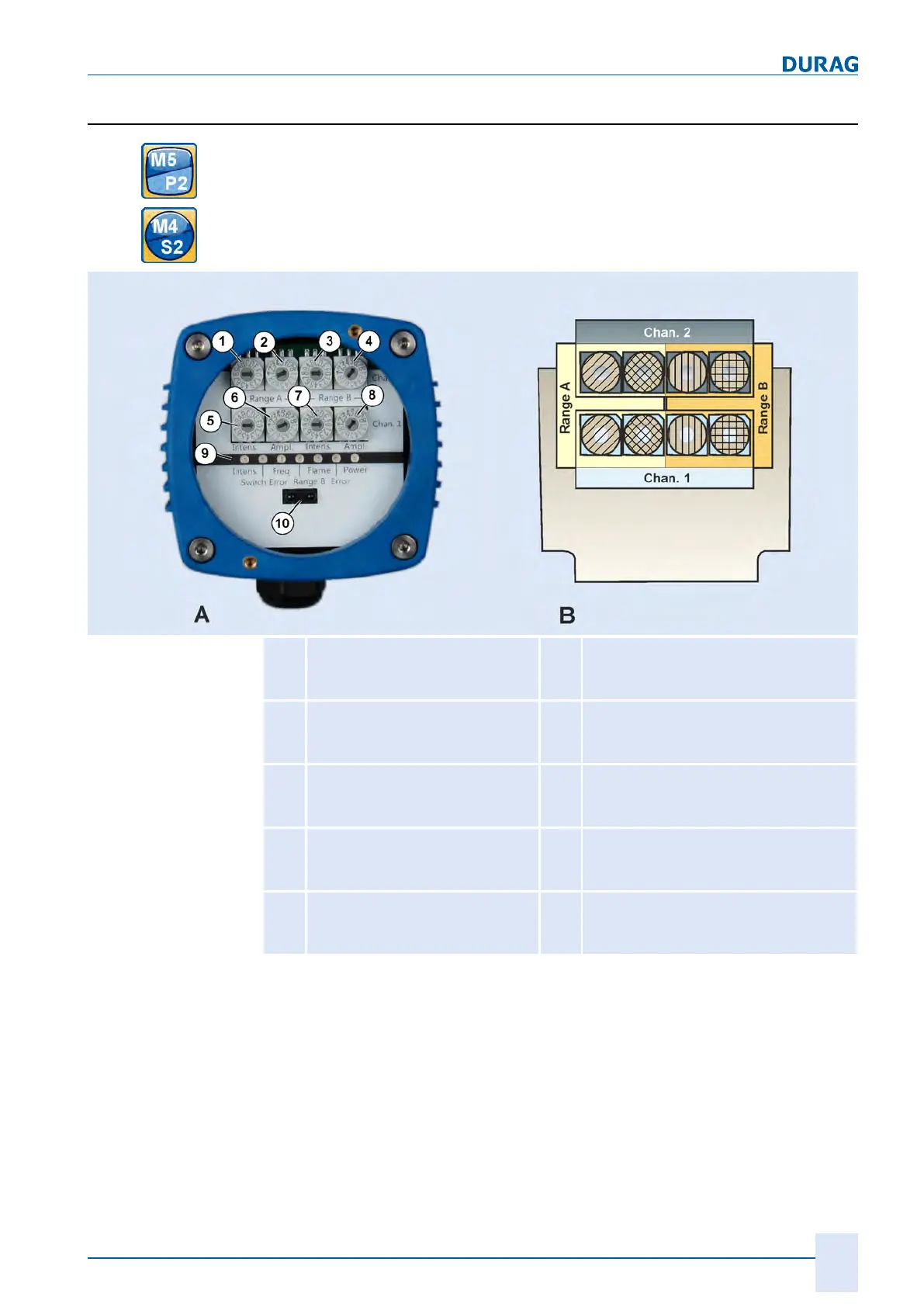
6.2.4 Front panel (all types)
To operate the rotary switch you must unscrew the plug-in cover (see section 7.4.1 Re-
moving the plug-in cover (housing M5/P2) [}55]).
To operate the rotary switch you must open the housing (see section 7.4.5 Opening
housing M4 and S2 (for zone 1/21) [}58]).
1
Rotary switch for switching
threshold of intensity of channel
2 for range A
6
Rotary switch for gain characteristic
curve of channel 1 for range A
2
Rotary switch for gain character-
istic curve of channel 2 for range
A
7
Rotary switch for switching threshold of
intensity of channel 1 for range B
3
Rotary switch for switching
threshold of intensity of channel
2 for range B
8
Rotary switch for gain characteristic
curve of channel 1 for range B
4
Rotary switch for gain character-
istic curve of channel 2 for range
B
9
Row of LEDs (see next table for mean-
ings of the LEDs)
5
Rotary switch for switching
threshold of intensity of channel
1 for range A
10
IrDA interface
Fig.6.7: A: Front view of the flame monitor without plug-in cover (the figure shows the housing P2); the front
panel is pictured schematically in B.