7 | Installation and commissioning
D-LX 201/721
61
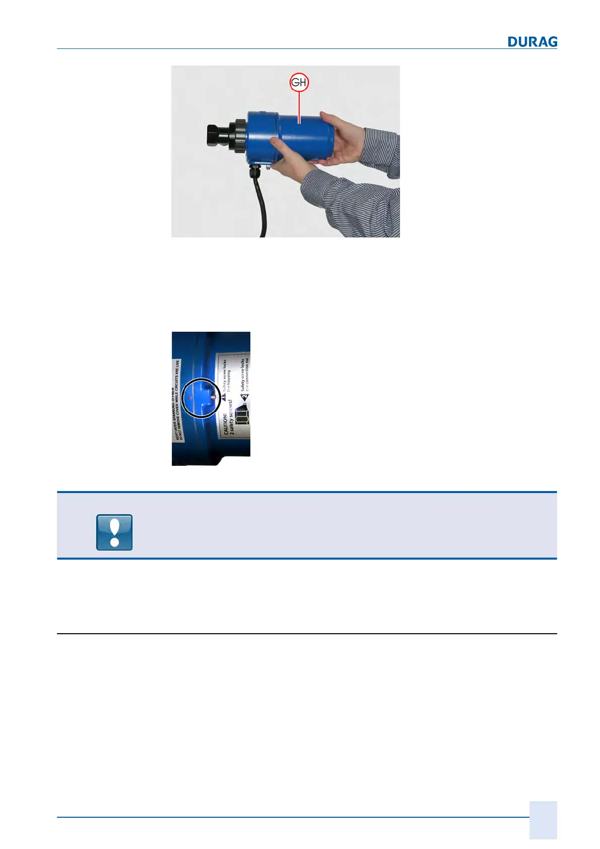
Fig.7.14: Move the cover onto the longitudinal device axis when sliding it on
2.
Carefully screw on the cover (
GH
) by turning it in a clockwise direction. The screw
connection is established via a thread, which also creates the pressure-tight seal.
It has proved useful to start by screwing on the cover with light pressure in an anti-
clockwise direction until the thread guide noticeably subsides. Then screw on in a
clockwise direction until the cover is lying securely on the base. This is the case
when the safety screw is right next to the red dot on the Ex middle part.
Fig.7.15: Correctly closed housing
NOTICE
If the thread is positioned correctly in the guide, the cover can be easily screwed on.
No tools are required
for this purpose!
Never use force to screw in the thread. This can damage the thread.
3.
Screw down the safety screw (socket head) by turning a few rotations in a clock-
wise direction, thereby securing the cover against being accidentally undone.
7.5 Electrical connection
Installation is performed based on the dimensional drawing for the flame monitor (see
section 11.3 Dimensional drawings [}101]). Electrical installation is performed based
on the local regulations and the connection diagram.
Direct switching of the fuel valves is not permitted.
The flame signal is a safety-relevant component. It may undergo a safety-relevant
evaluation, exclusively via the relay contact for the flame signal. All other signals (ana-
logue output, Modbus signal) are not suitable for this purpose! They are solely for in-
formation purposes!