7 | Installation and commissioning
D-LX 201/721
65
Red
Blue
Grey
Pink
Green/yellow
Ready for operation
Yellow
Flame ON
Green
White
Brown
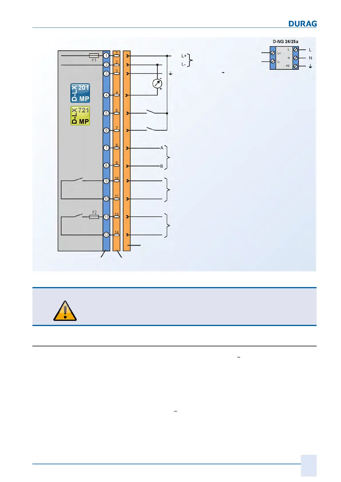
DC network
AC power supply
(accessories)
Functional earth (FE)
Terminal strips
Fieldbus: RS485/Modbus RTU
Range switching
External reset
Analogue output (0/4 ... 20 mA)
Orange
Black
Violet
Cable jack
MP 3 panel plug (on
flame monitor)
Protective
earth
Fig.7.18: Connection diagram for D-LX 201/721 with panel plug
CAUTION
At the "ready for operation" contact output, only non-reactive components may be
operated via an external fuse (for information on the permissible electrical currents,
see section 10 Appendix: Technical data [}93]). This measure provides protection
against contact welding in accordance with EN298.
7.6 Cables and screening
The flame monitor is designed for the switching of 24 V voltages via the "ready for op-
eration" contact and the flame contact. When switching loads via these contacts, elec-
tromagnetic disturbances may occur, which may interfere with other circuits in the
event of long relocations.
It is recommended that a sub-distribution unit be installed in the vicinity of the flame
monitor and the further cabling be carried out with separate, screened lines.
The individual wires can be determined based on the system-specific requirements.
The cross-section for the 24 V
supply line must be large enough to ensure that
R =
10 Ω
is not exceeded for each wire. The flame monitor will then continue to work reli-
ably at
24 V – (200 mA x 2 x 10 Ω) = 20 V