7 | Installation and commissioning
D-LX 201/721
53
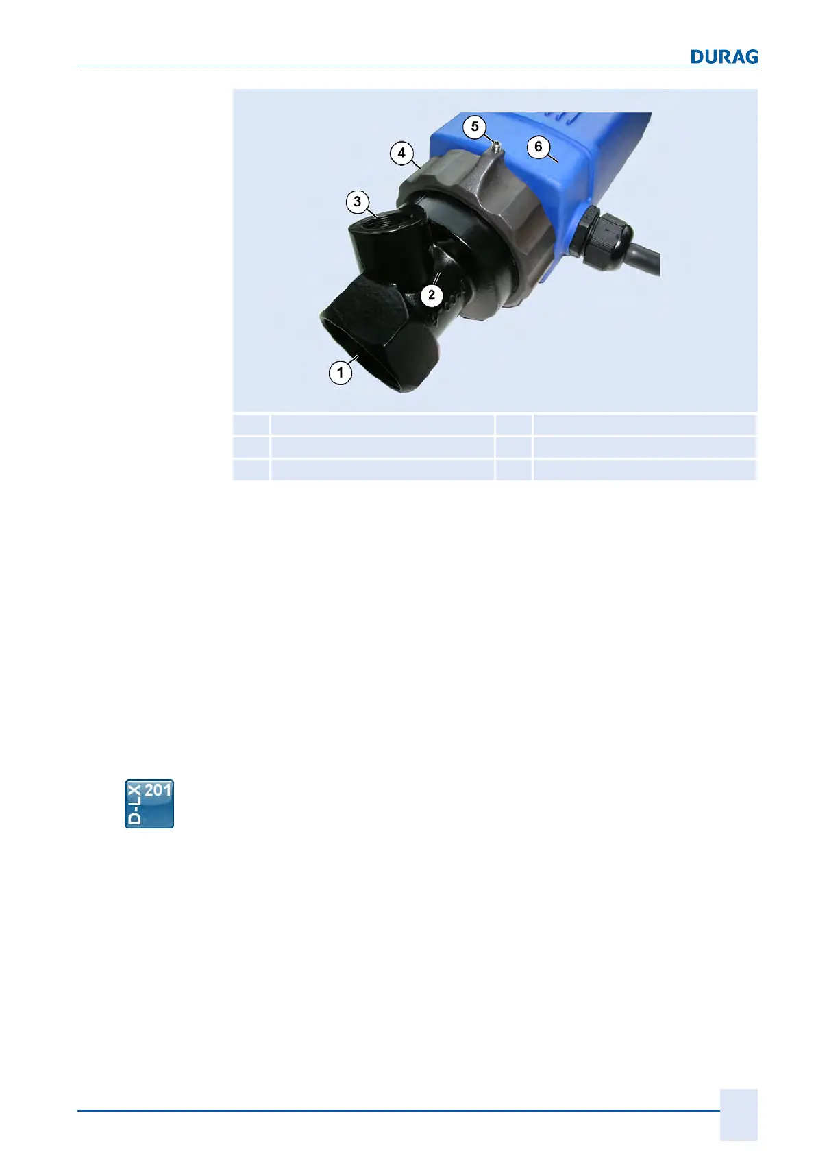
1
Sighting tube connection
4
Connecting nut
2
Front part
5
Locking screw
3
Purge air connection
6
Middle part
Fig.7.1: Middle part screwed onto the front part (figure shows housing P3)
The front part of the flame monitor with purge air connection (
3
) is then screwed onto
the sighting tube.
The middle part (
6
) with the connecting nut (
4
) can then be tightened by hand.
The flame monitor should be checked regularly in order to verify that the lens is clean
and that it is seated securely in the front part.
The connecting nut is fitted with a secure attachment device in the form of a locking
screw (
5
) (2-mm socket head wrench). Installation should be carried out correctly us-
ing a tightened locking screw.
In order to ensure optimal alignment on the flame, different ball adjustment flanges in
series D-ZS 033 are available:
Dimensional drawing of ball adjustment flange D−ZS 033-I
Different ball adjustment flanges in series D-ZS 033 are available (see section5.2 Ac-
cessories [}31]), e.g. ball adjustment flange D-ZS 033-I: