8 | Flame monitor settings
76
D-LX 201/721
The switching positions (1 … 8, 1‘ … 8‘) are available on the rotary switches for select-
ing the gain characteristic curves. Select "1" for gain characteristic curve V1, "2" for V2
etc. In addition to the usual gain characteristic curves V1…V8 gain characteristic
curves V1‘ … V8‘ are also available. They offer gain like characteristics V1 … V8 but
with additional digital filtering.
With most oil and gas combustions the filtering allows significantly better separation
between the flame that is to be monitored and the background radiation. With coal
combustions in individual cases gain characteristic curves without additional filtering
can allow better monitoring of the flame.
The rotary switches do not have end stops. From switching position 8’, they will
continue on to switching position 1 (and from 8 to 1’).
The rotary switches are electronic components and are correspondingly sensitive. In
order to avoid any damage, do not push too hard on the switches (max. 20 N).
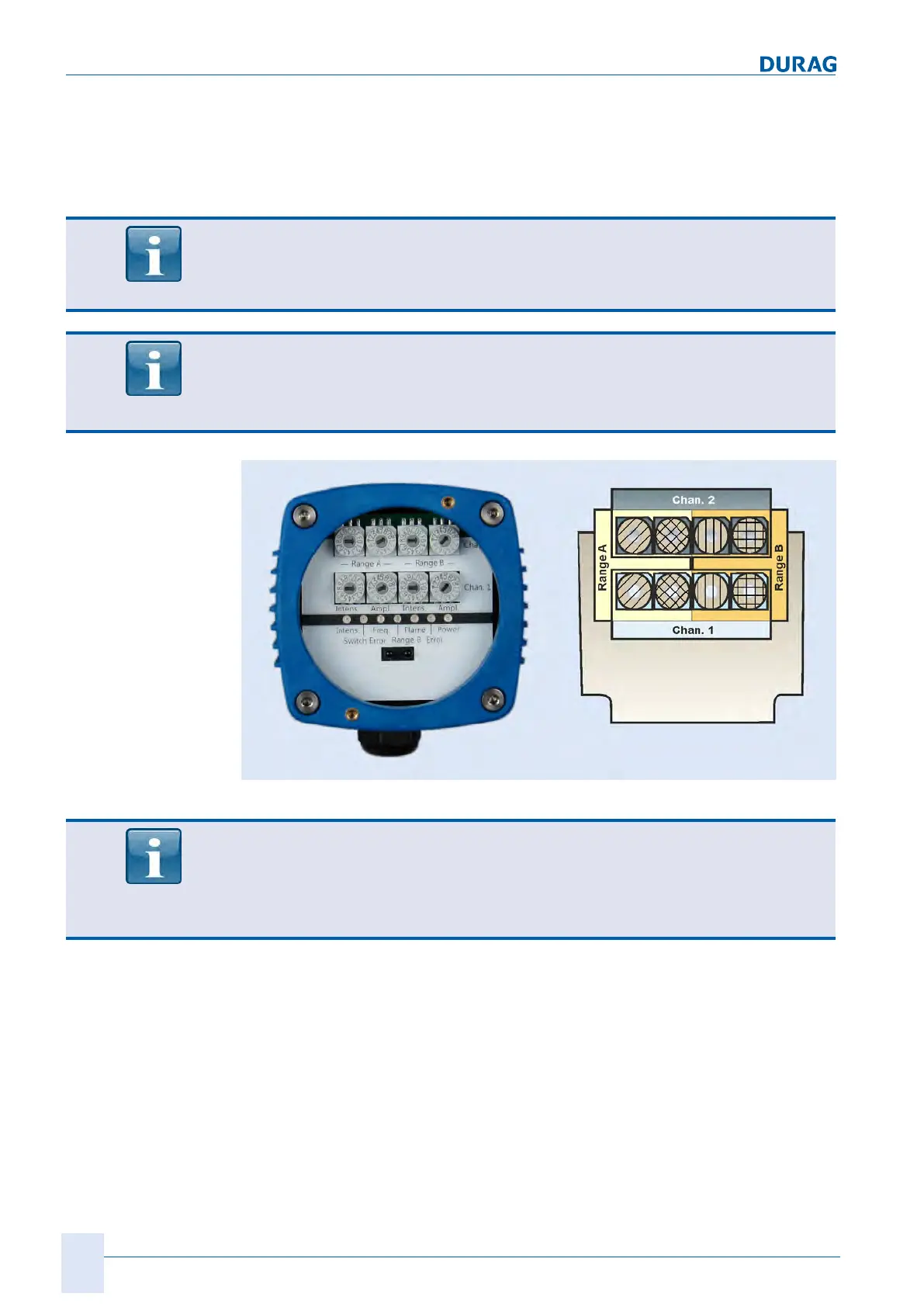
Fig.8.5: Front panel
The rotary switches positioned one on top of the other (right-hand image: rotary
switches with identical hatching) must be set to the
same position
within 8 secs.
In the event of discrepancies between the channels/rotary switches, the red "Switch
error" LED will light up, and an error shutdown (see section 9.5.1 Fault messages
[}91]) will be performed by the flame monitor after 8 secs.
After the settings have been made:
Check the seal in the plug-in cover for damage. Position the plug-in cover so that it
lies evenly on the cover. If necessary, rotate the plug-in cover to align it with the cover.
Screw down the plug-in cover with the two socket head screws. This seals the housing
and guarantees the IP protection. The supply voltage can be switched back on again.