Model 360/361 Control Valves
Dyna-Flo Control Valve Services Ltd.
Phone: 780 • 469 • 4000 Toll Free: 1 • 866 • 396 • 2356 Fax: 780 • 469 • 4035 Website: www.dynafl o.com
P-360M1019A
11
Operation, Parts, and Instruction Manual
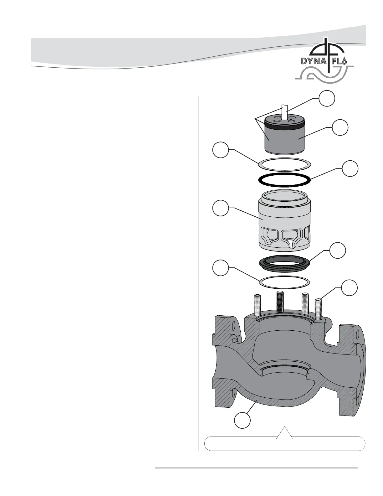
Figure 9 Standard Trim Parts Removal (Steps 1 - 6)
DISASSEMBLY (Continued)
TRIM PARTS REMOVAL
For Reduced Trim:
A Remove the cage adapter ring (Key 24). Refer to Figure
37. NOTE: 6x4 inch valve do not use a cage adapter.
B Remove the cage adapter gasket (Key 25), metal shim
(Key 21), and spiral wound gasket (Key 20).
For 8 inch valve assemblies:
A Remove the load ring (Key 23). Refer to Figure 38.
1 Remove the metal shim (Key 21) and spiral wound
gasket (Key 20) if they haven’t already been removed.
Refer to Figure 9.
2 Remove the valve stem (Key 5) / valve plug (Key 3)
assembly from the valve body (Key 1), refer to Figure 9.
Refer to Plug Seal Removal section for disassembly
instructions.
3 Carefully remove the cage (Key 19).
4 Remove the seat ring (Key 15) and seat ring gasket (Key
12). For Soft Seat valves: Remove the disk retainer (Key
18), PTFE disk (Key 17), disk seat (Key 16), and seat ring
gasket (Key 12). Refer to Figure 38.
5 For Reduced Trim: Remove the seat ring adapter (Key
13) and seat ring adapter gasket (Key 14). Refer to Figure
37. NOTE: 6x4 inch valves do not use a seat ring adapter.
6 Clean and inspect all parts for damage, especially gasket
seal surfaces. Replace all damaged parts and gaskets with
new parts as necessary, gaskets cannot be reused.
PACKING PARTS REMOVAL
WARNING: Compressed gasses could be trapped between
packing rings.
NOTE: For Live Loaded Packing refer to Figure 31 and the Live
Loaded Sliding Stem Packing Manual (P-LLPS).
1 Using a blunt or rounded tool or rod, carefully tap the
packing parts (Keys 30, 31, 32, 33, and 34) out of the
packing bore of the bonnet (Key 26). A mechanic’s pick
set can also be used to pull packing parts from the bore.
For other packing arrangements, refer to Figures 29 to 31.
PLUG / STEM
ASSEMBLY
5
3
20
19
12
21
2
1
15