Model 360/361 Control Valves
Dyna-Flo Control Valve Services Ltd.
Phone: 780 • 469 • 4000 Toll Free: 1 • 866 • 396 • 2356 Fax: 780 • 469 • 4035 Website: www.dynafl o.com
P-360M1019A
19
Operation, Parts, and Instruction Manual
ASSEMBLY (Continued)
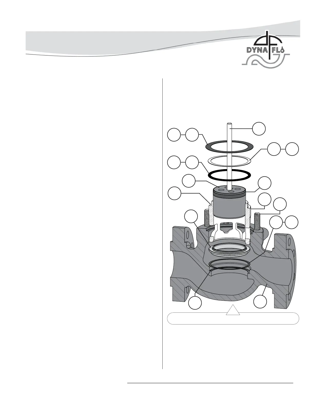
TRIM PARTS ASSEMBLY
NOTE: Spiral wound gaskets (Keys 20) make their seal by
being crushed and cannot be reused.
1 Apply nickel anti-seize (Key A) to the seat ring pocket
of the valve body (Key 1) and top surface of the seat ring
gasket (Key 12). Install the seat ring gasket into the valve
body (Key 1). Refer to Figure 23.
2 For Reduced Trim: Install the seat ring adapter (Key
13) into the valve body. Apply nickel anti-seize (Key A)
to the top of the seat ring adapter and top of the second
seat ring gasket (Key 14) and install it onto the seat ring
adapter. Refer to Figure 37. NOTE: 6x4 inch reduced trim
does not use a seat ring adapter, 6x4 inch valves have a
special seat ring (Key 15).
3 Install the seat ring (Key 15) into the valve body (Key 1).
Refer to Figure 34 for Angle Body valve assemblies.
For Soft Seat Valves: Install the disk seat (Key 16) onto
the seat ring gasket (Key 12). Install the PTFE disk (Key
17) onto the disk seat. Install the disk retainer (Key 18)
onto the PTFE disk. Refer to Figure 36.
4 Install the cage (Key 19). Install the baffl e (Key 50) and
cage retainer for Low-Noise trim, refer to Figure 35 for
Low-Noise trim.
5 Apply Lubriplate® No. 105 (Key C) to the side of the valve
plug (Key 3) (Refer to Figures 17, 18, & 20). Install the
valve plug assembly into the cage (Key 19) (Refer to Figure
23).
6 Apply nickel anti-seize (Key A) to the gasket surface of
the cage (Key 19) or cage retainer (Key 49) and top
surface of the spiral wound gasket (Key 20), metal shim
(Key 21), and bonnet gasket (Key 22). Install the gaskets
and shim as shown in Figure 23 or 35 for Low-Noise trim.
For Low-Noise Valves: Install the bonnet spacer (Key
26A) as shown in Figure 35. Apply nickel anti-seize (Key A)
to the gasket seating surface of the bonnet spacer
(Key 26A) and top surface of the bonnet gasket (Key 22)
and install. Install the load ring (Key 23).
For 8 Inch Valves: Apply nickel anti-seize (Key A)
to the gasket seating surface of the valve body (Key 1)
and top surface of the bonnet gasket (Key 22) and install.
Install the load ring (Key 23). Refer to Figure 38.
Figure 23 Trim Parts Assembly
BONNET INSTALLATION
Before You Begin:
• Read Safety Caution (Page 2).
• Clean and inspect all parts.
• Replace or repair damaged parts. Replace all soft parts
(Seals, o-rings, gaskets, live loaded packing).
7 For Reduced Trim: Install the cage adapter (Key 24).
Apply nickel anti-seize (Key A) to the top of the cage
adapter and top surface of the cage adapter gasket (Key
25) and install. Refer to Figure 37. NOTE: 6x4 inch
reduced trim does not use a cage adapter, 6x4 inch
valves have a special cage (Key 19).
A 22
21 A
A 20
A
A
15
19
2
5
7
3
12 A
1