Dyna-Flo Control Valve Services Ltd.
Phone: 780 • 469 • 4000 Toll Free: 1 • 866 • 396 • 2356 Fax: 780 • 469 • 4035 Website: www.dynafl o.com
Model 360/361 Control Valves
P-360M1019A
20
Operation, Parts, and Instruction Manual
ASSEMBLY (Continued)
BONNET INSTALLATION (Continued)
1 Apply nickel anti-seize (Key A) to the gasket sealing
surface of the valve bonnet (Key 26).
2 Lift and lower the valve bonnet (Key 26) into place over
the valve stem (Key 5). Be careful not to damage either
the stem, bonnet, or valve body (Key 1).
3 Apply nickel anti-seize (Key A) to the threads of the
bonnet studs (Key 2). Thread the bonnet nuts (Key 28)
onto the bonnet studs until hand tight.
4 Stroke the valve a few times to center the valve trim.
5 It may help to install the packing follower (Key 22) during
bonnet installation to act as a visual cue to indicate areas
of over or under tightening. If the packing follower begins
to bind or appear lop-sided, this is an indication that
torquing procedures in Steps 6 & 7 need to be altered to
correct areas that need more tightening or less. The
packing follower should remain centered during the
torquing process.
6 Follow proper body-to-bonnet bolting procedures. Begin to
torque the bonnet nuts (Key 28) ¼ (25%) of the torque
value listed in Table 5, torque the nuts in a crisscross
pattern as shown in Figure 25. Hot torquing the valve nuts
is not recommended.
7 Continue tightening the bonnet nuts (Key 28), increasing
the torque by ¼ (25%) of the fi nal torque specifi cation
each round of tightening while repeating the crisscross
pattern until the fi nal torque specifi cation is reached.
8 Double check the tightness of all nuts by torquing the
nuts to the fi nal torque specifi cation one more time after
the fi nal torque value was reached.
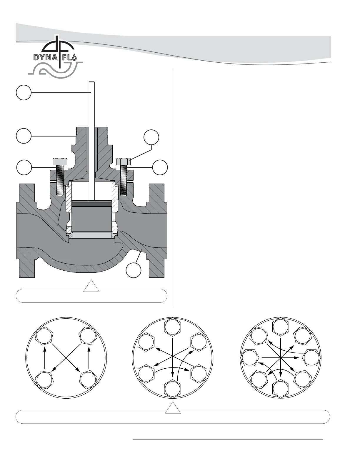
Figure 24 Bonnet Installation
1
2
3
4
1
2
3
4
5
6
1
2
34
5
6
7
8
Figure 25 Bolt Tightening Pattern Diagram
SAMPLE BOLT CONFIGURATION
2 A
5
28
26
1