Model 360/361 Control Valves
Dyna-Flo Control Valve Services Ltd.
Phone: 780 • 469 • 4000 Toll Free: 1 • 866 • 396 • 2356 Fax: 780 • 469 • 4035 Website: www.dynafl o.com
P-360M1019A
21
Operation, Parts, and Instruction Manual
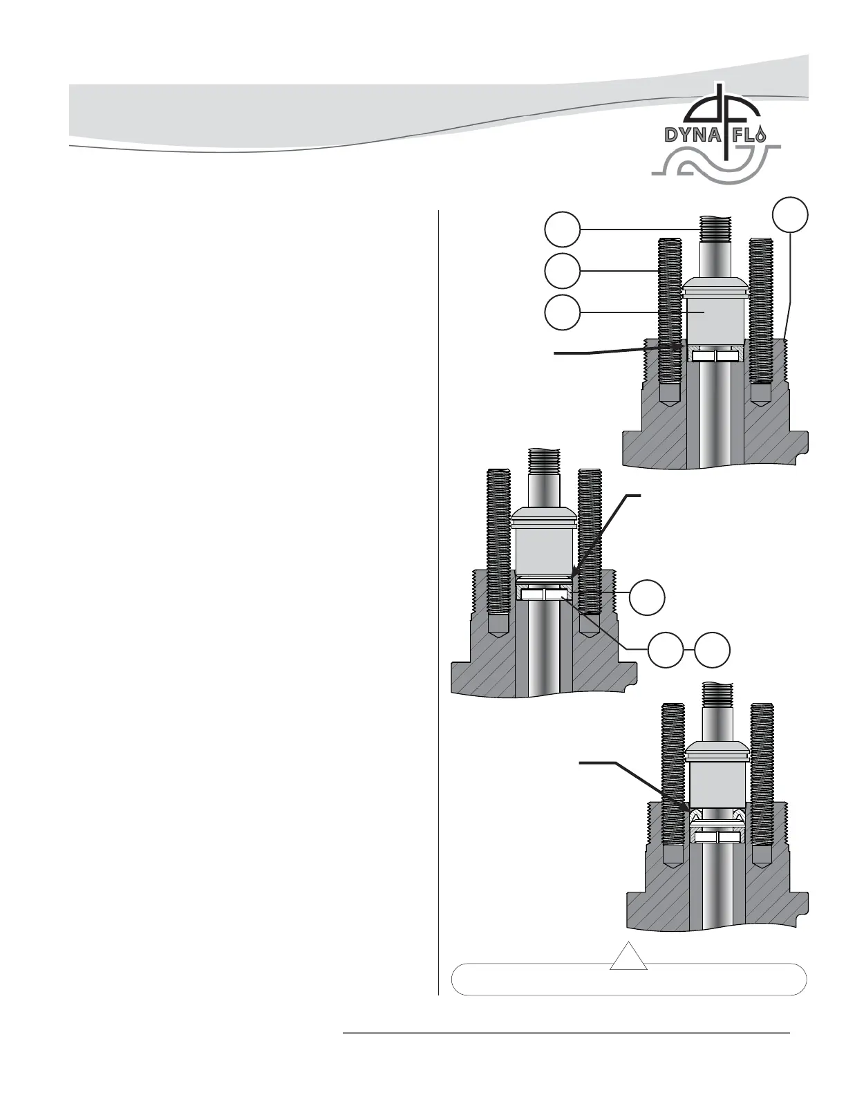
Figure 26 Proper Packing Ring Installation
ASSEMBLY (Continued)
PACKING INSTALLATION
For Live Loaded packing instructions see the Live Loaded
Sliding Stem Packing Manual (Part Number P-LLPS). For other
packing arrangements refer to Figures 27, 29, 30, & 31.
Lubricants Required:
• Permatex® Nickel Anti-Seize or equivalent (Key A)
• Dow Corning Molykote® 111 or equivalent (Key B)
• Lubriplate® No. 105 Grease or equivalent (Key C)
NOTE: To prevent trapping air between packing during
installation, it is recommended that packing rings be installed
one at a time using the packing follower (Key 35) to push
the packing rings in place. Do not force packing rings below
the chamfer of the packing bore before adding another ring,
packing rings should only be pushed down the thickness of the
added ring. Refer to Figure 26.
1 If the packing studs (Key 29) were replaced, removed,
or never installed, apply nickel anti-seize (Key A) to
the threads of the end of the stud without a material
stamp.
2 Thread the studs (Key 29) into the valve bonnet (Key 26)
anti-seize coated end fi rst until they are completely
threaded into the bonnet.
For Single Style (Spring-Loaded) Packing:
1 Apply Molykote® 111 (Key B) to the lower stem wiper (Key
30). Insert the lower stem wiper into the packing box ring
(Key 31). Insert the packing box ring into the packing bore
of the valve bonnet (Key 26).
2 Install the packing spring (Key 32).
3 Install the special washer (Key 33).
4 Apply Molykote® 111 (Key B) to the PTFE packing rings
(Key 34). Install the packing rings one ring at a time (as
shown in Figure 26) in the proper order and orientation as
shown in Figure 27. WARNING: For oxygen service do not
apply Molykote® 111, Molykote® 111 in oxygen service
applications can cause an explosion.
5 Install the packing follower (Key 35).
6 Install the upper stem wiper (Key 36).
5
29
35
TOP OF PACKING
BOX RING (KEY 31)
PUSHED DOWN TO BE EVEN
WITH THE BOTTOM OF THE
PACKING BORE CHAMFER.
26
TOP OF FIRST PTFE PACKING
RING (KEY 34) PUSHED
DOWN TO BE EVEN WITH
THE BOTTOM OF THE
PACKING BORE CHAMFER.
31
30 B
TOP OF SECOND PTFE
PACKING RING (KEY 34)
PUSHED DOWN TO BE EVEN
WITH THE BOTTOM OF THE
PACKING BORE CHAMFER.