Model 360/361 Control Valves
Dyna-Flo Control Valve Services Ltd.
Phone: 780 • 469 • 4000 Toll Free: 1 • 866 • 396 • 2356 Fax: 780 • 469 • 4035 Website: www.dynafl o.com
P-360M1019A
5
Operation, Parts, and Instruction Manual
UNPACKING VALVE FROM SHIPPING
CONTAINER
Special Tools Required:
• Properly Rated Lifting Straps (2 – 4 Straps) refer to Table 4
for actuator weights.
• Lifting Device (Example: Crane)
Check the packing list, verify that the list includes all the
materials in the shipping container before unpacking. Valve
information can be found on the nameplate (Key 47). Refer to
Figure 2 for nameplate location.
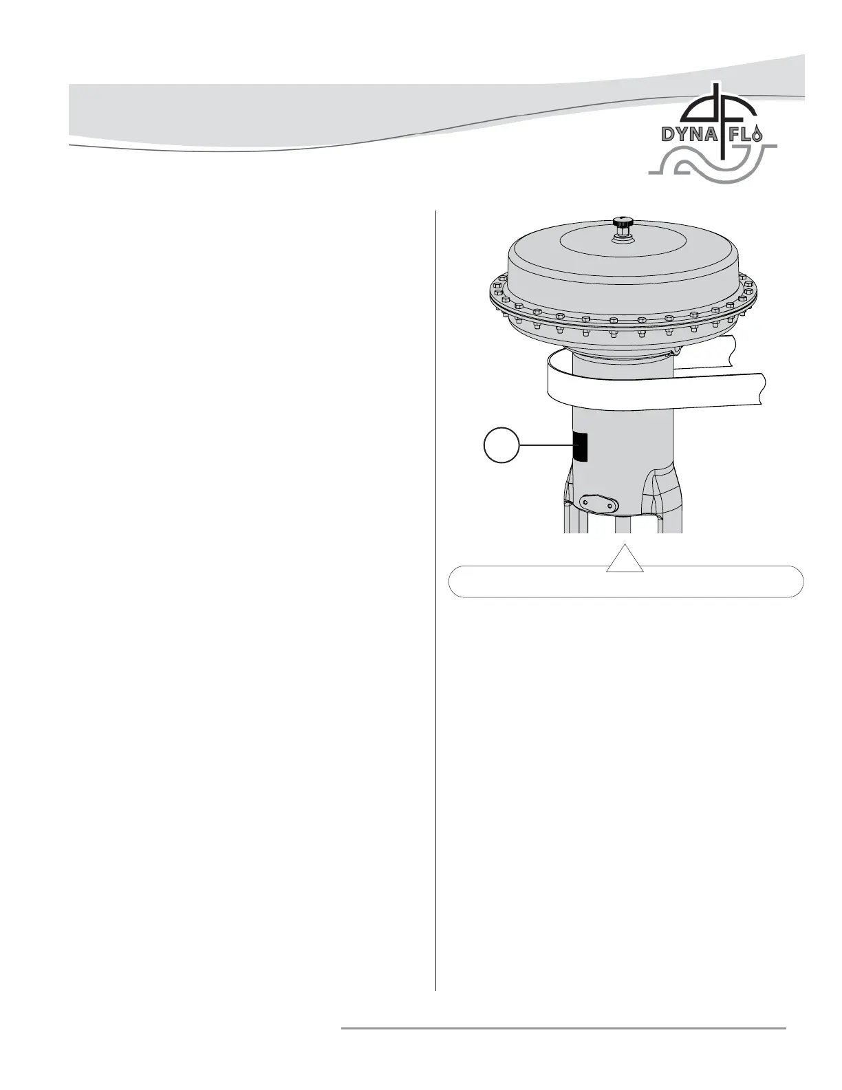
When lifting the valve from shipping container, place properly
rated lifting straps securely around the neck of the actuator,
refer to Figure 2 for strap placement. Straps should be placed
to avoid damage to tubing and other mounted accessories.
For valve assemblies without an attached actuator, use caution
when lifting or positioning straps so as not to damage the valve
stem.
Lift the valve/actuator assembly using proper lifting techniques.
INSTALLATION
Before You Begin:
• Read the General and Scope section of this manual (Page 2).
• Read Safety Caution (Page 2).
• Sudden movement of actuator can cause damage or injury.
It helps to have the actuator de-energized.
• Use safe work practices and lock out procedures before
placing valve in-line.
NOTE: For butt weld valve bodies, depending on the body
material, post-weld heat treatment might be required. Soft
parts, seals, some metal trim, threading and shrink-fi t parts
can be damaged by post-weld heat treatment. If post-weld heat
treatment is required, it is recommended that all internal valve
parts be removed from the valve body. Contact Dyna-Flo for
more information.
Parts Required:
• Appropriate Line Flange Nuts and Bolts
• Appropriate Line Flange Gaskets
• If the valve has small internal fl ow passages such as
Anti-Cavitation or Low-Noise trim, the installation of an
upstream strainer should be considered to prevent clogging
of these small passages.
Figure 2 Actuator Lifting Suggestions
Installation Steps:
1 Check the packing box bolting (Key 38) for proper
tightness. Refer to Packing Installation on Page 20 for
proper packing tightening instructions.
2 The valve assembly may be installed in any position
unless limited by vibration considerations, it is however
recommended that the valve be installed with the valve
stem (Key 5) perpendicular to the ground. NOTE: For
some non-vertical orientations, the valve actuator may
need to be supported.
3 Install the valve with fl ow through the valve in the
direction shown by the fl ow arrow on the valve body.
4 Install the appropriate line fl ange gaskets.
5 Apply Permatex
® Nickel Anti-Seize to the threads of the
fl ange studs and install.
6 When possible, before tightening the line bolting, stroke
the valve and check for smooth operation through the full
stroke. Unsteady valve stem movement could be an
indication of an internal problem.
7 Tighten the line fl ange bolting in even increments in a
crisscross pattern until the correct line bolt torque
specifi cation is reached.
LIFTING STRAP
47