Dyna-Flo Control Valve Services Ltd.
Phone: 780 • 469 • 4000 Toll Free: 1 • 866 • 396 • 2356 Fax: 780 • 469 • 4035 Website: www.dynafl o.com
Model 360/361 Control Valves
P-360M1019A
4
Operation, Parts, and Instruction Manual
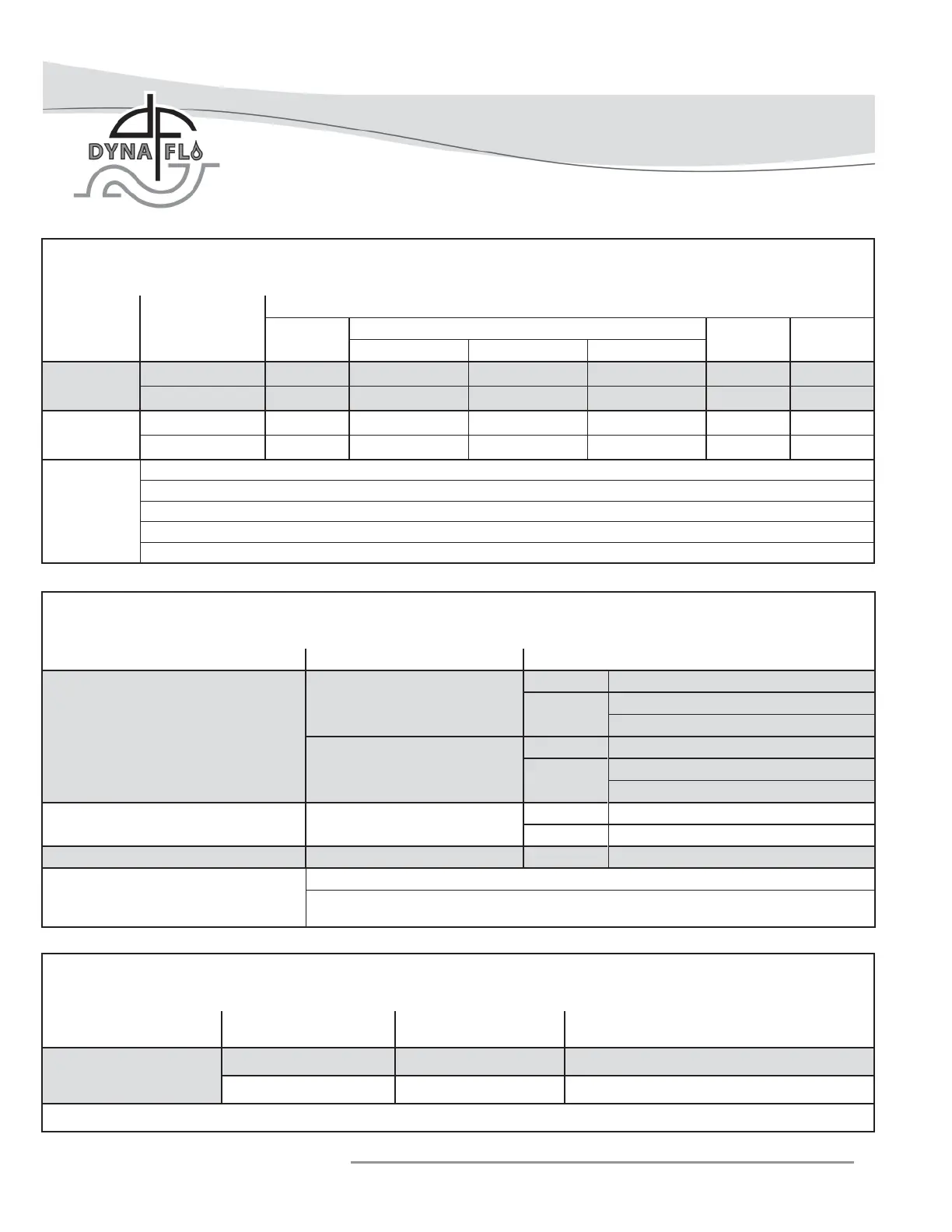
Table 2
Standard Shut-Off Classifi cations (in accordance with ANSI/FCI 70.2 and IEC 60534-4)
Valve Trim Seat Option Shut-Off Class
All
(Except Anti-Cavitation)
PTFE (Soft Seated)
Standard Class V (Air Test)
Optional
Class V
Class VI
(1)
Metal
Standard Class IV
Optional
Class V
(2)
Class VI
(1)
Anti-Cavitation 1 Stage Metal
Standard Class IV
Optional Class V
Anti-Cavitation 2 Stage Metal Standard Class V
Notes:
1 - Refer to Table 3.
2 - Class V shut-off requires a spring-loaded seal ring, radius-seat plug, and wide-bevel
seat ring. Not available with 8 inch port quick opening cages.
Table 1
Available Valve Confi gurations
Valve Model
Valve Size
Inch
End Connection
NPT
(1)
RF
(2)
and RTJ
(3)
(Flanged)
BWE
(4)
SWE
(5)
ASME Class 150 ASME Class 300 ASME Class 600
360
1 / 1-1/2 / 2
3 / 4 / 6 / 8
360A
1 & 2
3 / 4 / 6
Notes:
1 - NPT = Screwed.
2 - RF = Raised Face.
3 - RTJ = Ring Type Joint.
4 - BWE = Butt Weld (ASME Class 600 Only).
5 - SWE = Socket Weld (ASME Class 600 Only).
Table 3
Available Valve Confi gurations for Class VI Shut-Off (in accordance with ANSI/FCI 70.2 and IEC 60534-4)
Valve Model
Port Size
Inch
Valve Seat Minimum Seat Load
360
Refer to Table 23 for Trim
≥3.4375≤7 Metal
(1)
300 lbs./lineal inch
≥3.4375≤7 PTFE Consult Dyna-Flo
Note: 1 - Class VI shut-off requires a spring-loaded seal ring, radius-seat plug, and wide-bevel seat ring.