Dyna-Flo Control Valve Services Ltd.
Phone: 780 • 469 • 4000 Toll Free: 1 • 866 • 396 • 2356 Fax: 780 • 469 • 4035 Website: www.dynafl o.com
Model 360/361 Control Valves
P-360M1019A
6
Operation, Parts, and Instruction Manual
INSTALLATION (Continued)
AIR PIPING
WARNING:
Property damage, environmental harm, and personal injury can result from the use of supply gas other than clean,
non-corrosive, oil and moisture free air. Do not exceed the supply pressure indicated on the serial plate located on the actuator.
Before You Begin:
Note: Standard actuators accept ¼” (6 mm) NPT connections.
• Refer to the appropriate actuator instruction manual when necessary.
Piping Installation Steps:
1 Use 3/8” (outside diameter) tubing (or equivalent) for air lines.
2 Install the required line vents, valves, drains, seals, and fi lters to the actuator.
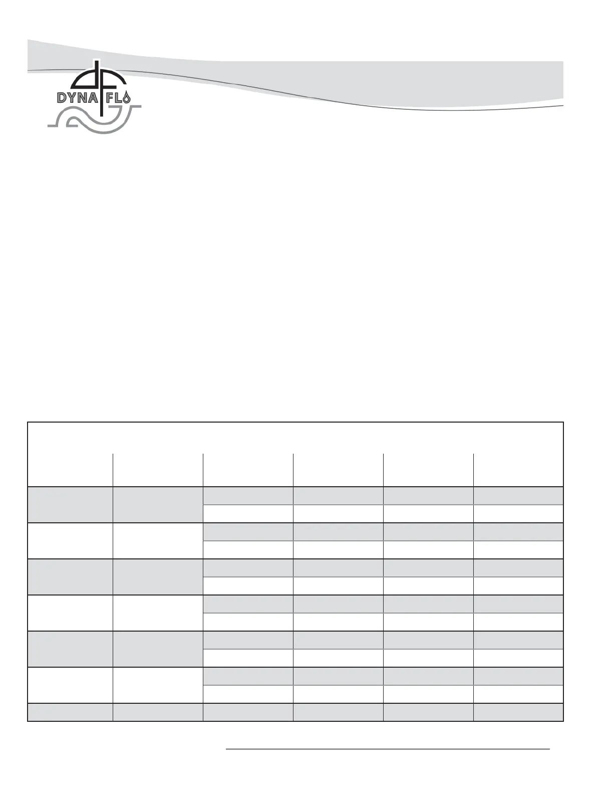
Table 4
Valve Body / Actuator Confi gurations and Approximate Weights
Valve Size
(inch)
Body Only
lb (Kg)
With Fail Open
Actuator Size
Valve and Actuator
Assembly Weight
lb (Kg)
With Fail Close
Actuator Size
Valve and Actuator
Assembly Weight
lb (Kg)
1 30 (14)
DFO - 1046 66 (30) DFC - 1046 64 (29)
DFO - 1069 70 (32) DFC - 1069 78 (26)
1-1/2 45 (20)
DFO - 1046 81 (37) DFC - 1046 79 (36)
DFO - 1069 85 (39) DFC - 1069 93 (42)
2 85 (39)
DFO - 2069 136 (62) DFC - 2069 135 (61)
DFO - 2105 167 (76) DFC - 2105 175 (79)
3 125 (57)
DFO - 2069 176 (80) DFC - 2069 175 (79)
DFO - 2105 207 (94) DFC - 2105 215 (98)
4 170 (77)
DFO - 2105 252 (114) DFC - 2105 260 (118)
DFO - 2156 277 (126) DFC - 2156 291 (132)
6 350 (159)
DFO - 3156 466 (211) DFC - 3156 471 (214)
DFO - 3220 585 (266) DFC - 3220 604 (274)
8
900 (408) DFO - 3220 1135 (515) DFC - 3220 1154 (523)