Model 360/361 Control Valves
Dyna-Flo Control Valve Services Ltd.
Phone: 780 • 469 • 4000 Toll Free: 1 • 866 • 396 • 2356 Fax: 780 • 469 • 4035 Website: www.dynafl o.com
P-360M1019A
17
Operation, Parts, and Instruction Manual
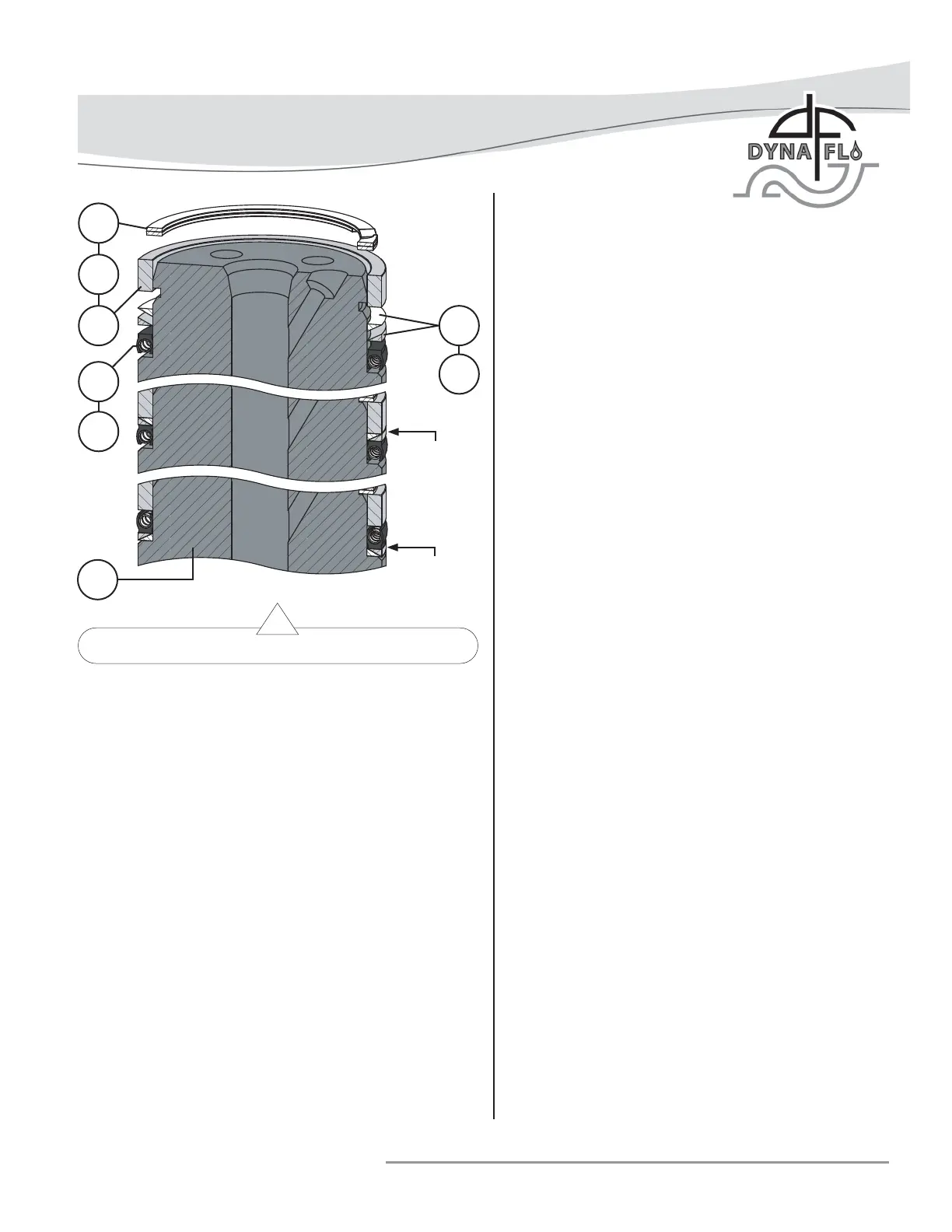
Figure 19 Plug Seal Assembly with Anti-Extrusion Ring
ASSEMBLY (Continued)
PLUG SEAL ASSEMBLY (Continued)
For Model 360 Three-Piece Plug Seal Ring Assemblies
with Anti-Extrusion Rings:
1 Apply Lubriplate® No. 105 (Key C) to the surface of the
seal ring (Key 8).
2 Install the seal ring (Key 8) onto the valve plug (Key 3),
refer to Figure 18 for proper seal ring orientation. NOTE:
8 inch valves are technically one-piece plug seals, 8 inch
valve assemblies use a seal ring only and do not make use
of a backup ring (Key 9) or retaining ring (Key 10).
3 Apply Lubriplate® No. 105 (Key C) to the anti-extrusion
ring (Key 11) and install the anti-extrusion ring on to the
valve plug as shown in Figure 19. NOTE: Anti-extrusion
rings are only used for valve assemblies rated to exceed
450ºF (232ºC).
4 Apply Lubriplate® No. 105 (Key C) to the backup ring
(Key 9) and install the backup ring onto the valve plug
(Key 3).
5 Apply Lubriplate® No. 105 (Key C) to the retaining ring
(Key 10) and install the retaining ring into the retaining
ring groove on the valve plug (Key 3).
6 Allow time for the seal ring material to shrink back to its
original size after being stretched over the valve plug
before installing the plug assembly into the cage (Key 19).
For Model 361 Valves:
NOTE: Replacement piston rings (Key 48) come in one piece.
Before installation it is necessary to break the piston ring into
two pieces. Do not saw or cut the piston rings. Use caution
when breaking piston rings as they can be easily damaged.
Piston Ring Vise Break Method:
Piston rings (Key 48) can be broken into two pieces using a vise
with smooth jaws or jaw softeners.
Special Tools Required:
• Vise
• Electrical Tape
1 Wrap electrical tape once around the outside diameter of
the piston ring (Key 48). Electrical tape will help contain
the piston ring while it is being broken. Refer to Figure 21.
2 Place the piston ring into the jaws of the vise as shown in
Figure 22.
3 Slowly compress the piston ring in the vise until the ring
snaps on both sides. If one side of the piston ring snaps
fi rst, continue compressing the piston ring until the other
side snaps as well.
Piston Ring Scoring Break Method:
If no vise is available, piston rings (Key 48) can be scored with
a knife and broken over a hard surface. Do not saw or cut the
piston rings in half.
1 Wrap electrical tape once around the outside diameter of
the piston ring (Key 48). Electrical tape will help contain
the piston ring while it is being broken. Refer to Figure 21.
2 Score (do not cut) the top surface of the piston ring.
3 Place half of the piston ring over the edge of a hard surface
(such as a table edge) so that the score marks are in a
parallel line with the edge of the hard surface.
4 Apply downward pressure to both sides of the piston ring
until it snaps in half.
5 Remove the electrical tape. Install each half of the broken
piston ring into the piston ring groove in the valve plug
(Key 3). Refer to Figure 20.
10
C
9
C
11
C
8
3
NOTE: KEY
11 IS TWO
PIECES AND
MUST BE
ARRANGED
AS SHOWN.
FLOW DOWN
ORIENTATION
FLOW UP
ORIENTATION