No. 60027, Issue 4. January 1998
5 Installation14
DX
Module
DX
Module
DX
Module
DX
Module
DX
Module
DX
Module
DX
Module
DX
Module
DX
Module
DX
Power
Module
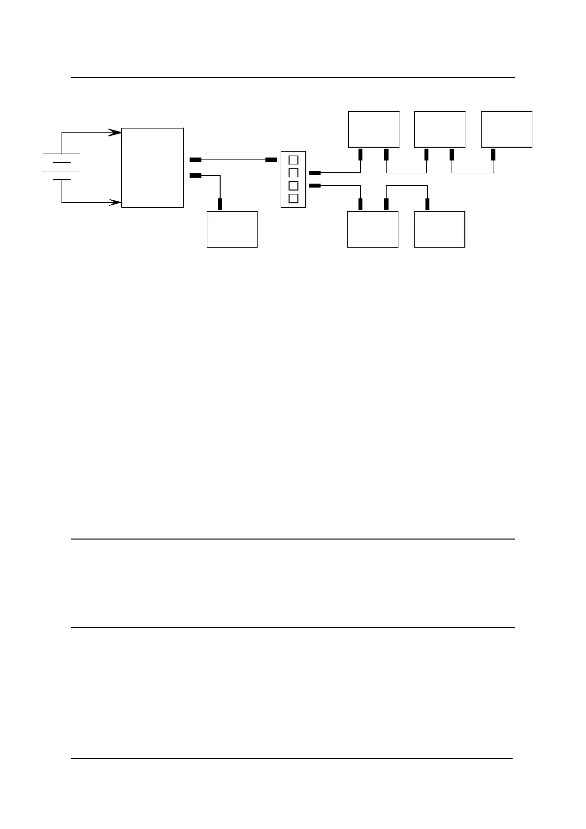
Battery
24V
Splitter Box
Mixed DXBUS Topology
DX modules normally have one or two DXBUS sockets for system
interconnections. Smaller DX modules may have a permanently mounted cable
terminated in a DXBUS plug, rather than DX sockets.
The star and mixed topologies both require the use of one or more DX Splitter
Boxes. A Splitter Box is a separate panel of four DXBUS sockets that may be
purchased from Dynamic or a Dealer.
The DX Splitter Box Part/Order Number is: DX-SKT-X4.
For lowest cost and simplicity the In-line topology is generally preferred, provided
the DXBUS length and voltage drop requirements described below can be met.
Warning If the SLM is between the PM and the Battery Charger:
1. Have as few as possible DXBUS cables between the SLM and the PM.
2. The DXBUS cables between the SLM and the PM must not total more
than 1 metre.
This will avoid unintended interaction between the SLM and the Battery Charger.