No. 60027, Issue 4. January 1998
5 Installation18
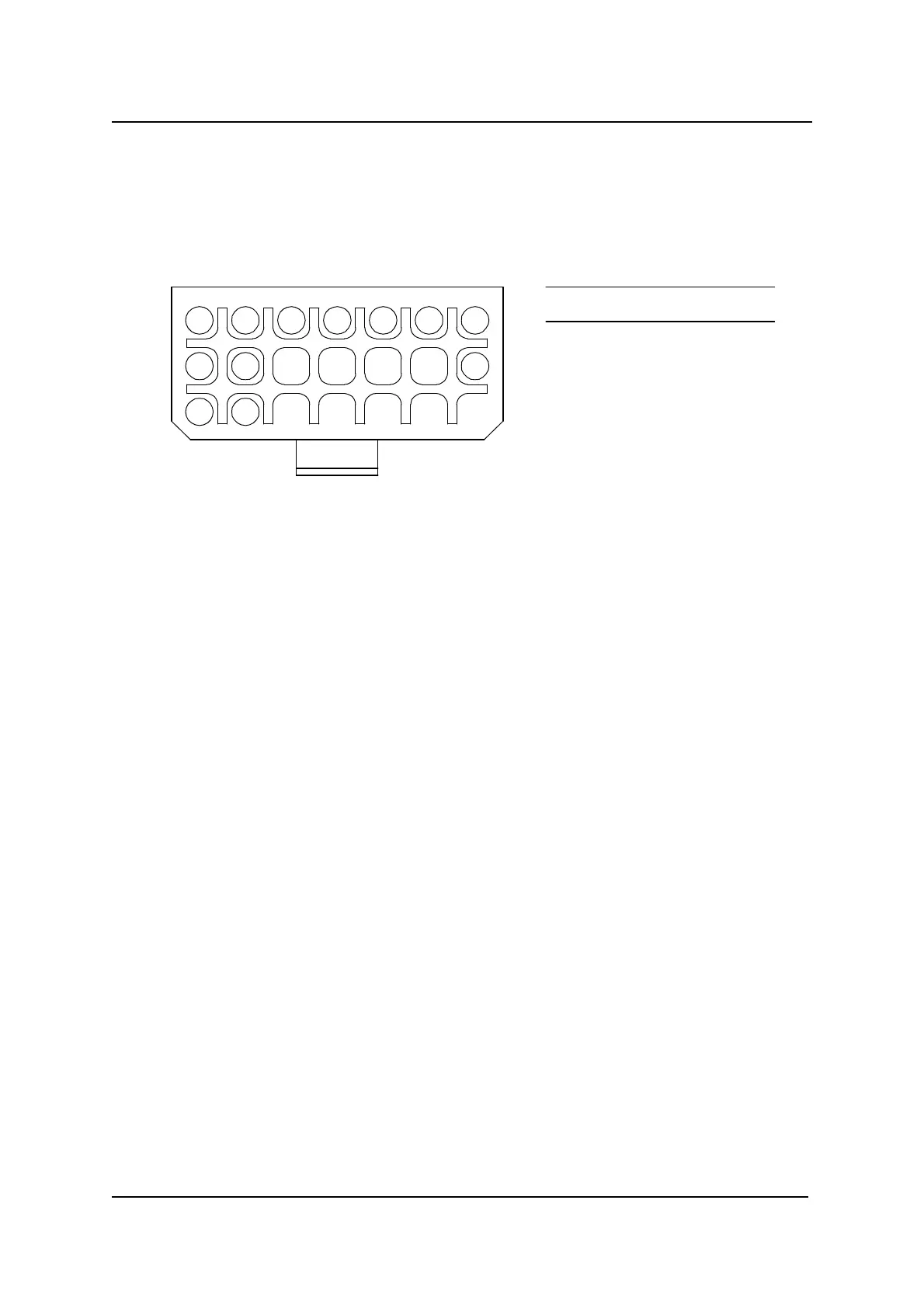
1
8
15
3 62
9
16
14
54 7
Pin
1
2
3
4
5
6
7
8
9
14
15
16
Function
DXBUS -
Side Lights -
Left Indicator -
Right Indicator -
13.5 V
Hazard In
Hazard Out
Battery -
Steering Power +
Battery - (spare)
DXBUS +
Lighting +
5.4 SLM 21 Way Connector
5.4.1 21 Way Connector Pin Definitions
Note : Other pins unused.
5.4.2 21 Way Connector Wires and Terminations
To build a matching connector
To build a matching connector to fit to the 21 way connector, the parts are :
DX 21W Plug Housing Part/Order Number GCN 0796
DX 21W Boot Part/Order Number GCN 0795
DX Positronics Contact, FC114N2 (Lge) Part/Order Number GCN 0793
DX Positronics Contact, FC116N2 (Med) Part/Order Number GCN 0797
DX Positronics Contact, FC120N2 (Sml) Part/Order Number GCN 0794
The DX Positronics Contacts are crimp terminals.