No. 60027, Issue 4. January 1998
5 Installation 15
Rct
Rct
Rca
Rca
5.3.3 DXBUS Length and Voltage Drop Restrictions
Due to signal distortion that increases with increasing DXBUS length, the total
length of all DXBUS cables must not exceed 15 metres in any topology.
Two of the DXBUS's four cores (DXB+ and DXB-) are used to supply power to the
modules and to the loads connected to them. A Positive Temperature Coefficient
(PTC) device in the Power Module limits the total DXBUS current to 12 A, to
protect the DXBUS wiring and connectors. The topology and cable lengths used
may reduce the DXBUS's upper limit to below 12 A.
For correct DX System operation the voltage drop on the DXBUS's DXB- wire due
to return currents, must not exceed 1.0 V between any two modules within the DX
System. Use a topology and module placement that reduces this voltage drop as low
as reasonably possible.
Voltage drops occur along the DXBUS due to the return of current back to the
battery through the small but finite resistance of the DXBUS cable and connectors.
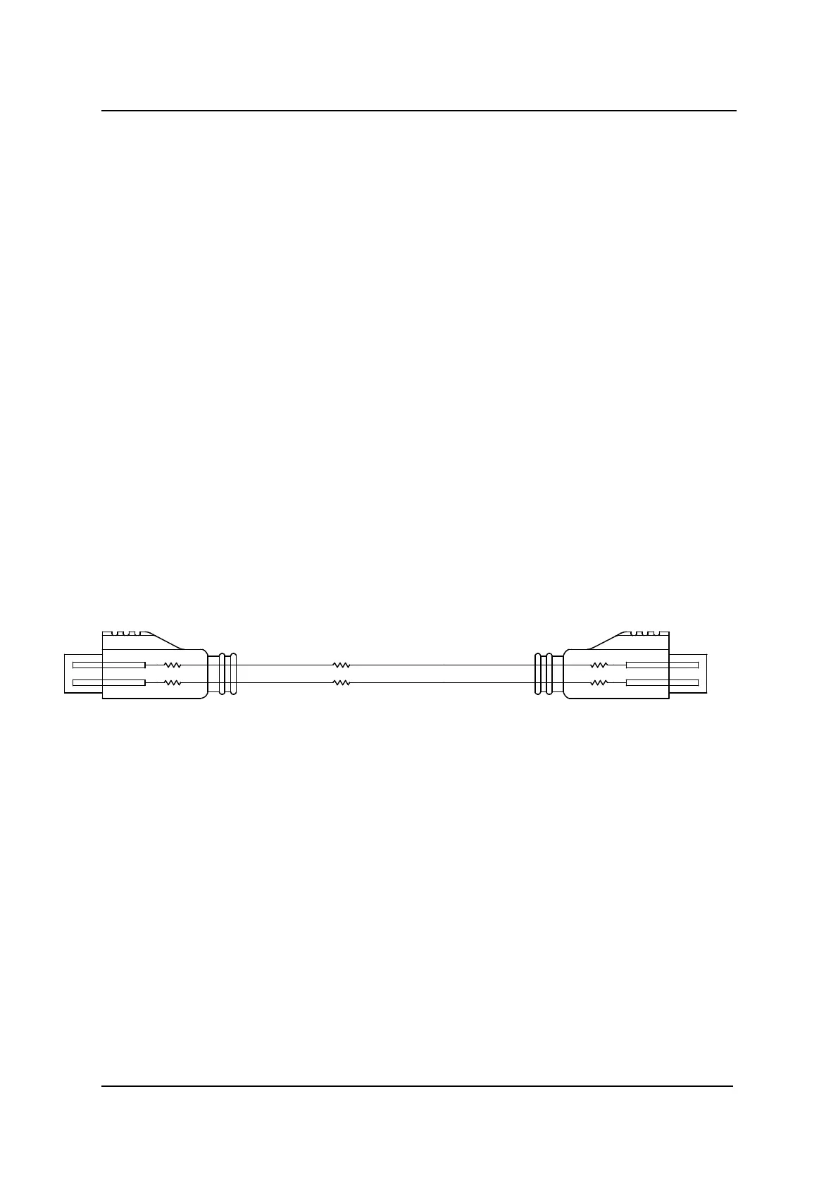
A DXBUS connector can be modelled as:
DXBUS Cable Model
R
ct
= contact resistance = 5 mOhm
R
ca
= cable resistance = 12 mOhm / metre