No. 60027, Issue 4. January 1998
5 Installation 19
Wire Sizes
The minimum wire sizes that must be used are :
Function Wire Size (minimum) Terminal Part
Positronic
Industries Ltd
DXBUS - 1.0 mm² FC116N2
Side Lights - 0.5 mm² FC120N2
Left Indicator - 0.5 mm² FC120N2
Right Indicator - 0.5 mm² FC120N2
13.5 V 1.0 mm² FC116N2
Hazard In 0.5 mm² FC120N2
Hazard Out 0.5 mm² FC120N2
Battery - 1.0 mm² motors < 10 A FC116N2
2.0 mm² motors > 10 A FC114N2
Steering Power + 1.0 mm² motors < 10 A FC116N2
2.0 mm² motors > 10 A FC114N2
DXBUS + 1.0 mm² FC116N2
Lighting + 1.0 mm² FC116N2
5.4.3 Power Supply from the DXBUS
The DXBUS is suitable for powering low speed servo motors and non TÜV
lighting, where the DX System current requirement is less than the 12 A DXBUS
rating. The DXBUS is not suitable for powering the SLM if TÜV compliance is
required.
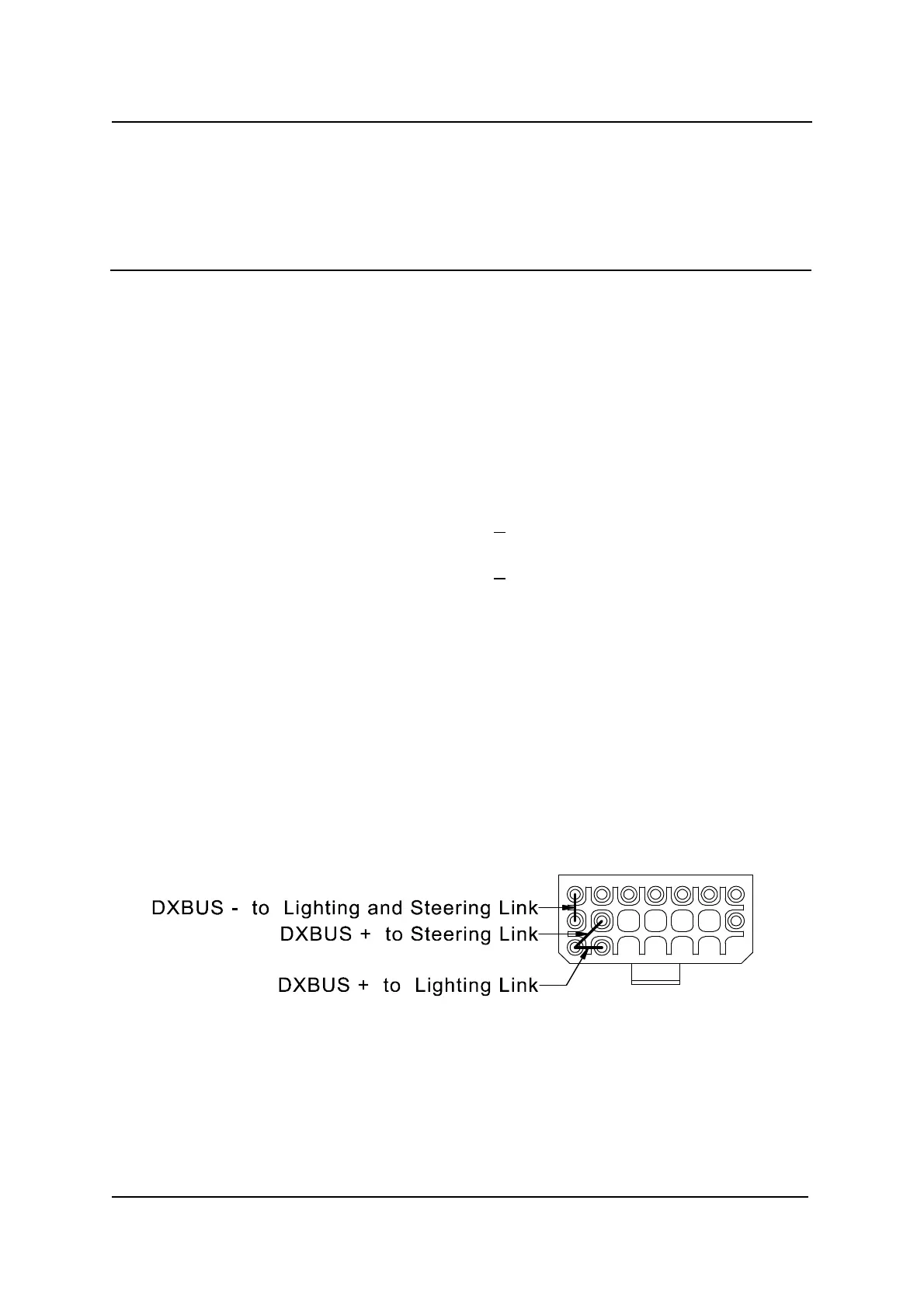
To power the lighting and servo motor from the DXBUS, links must be inserted to
short the DXBUS - pin to the Battery - pin, and the DXBUS + pin to the Steering
Power and Lighting + pins.