No. 60027, Issue 4. January 1998
5 Installation 25
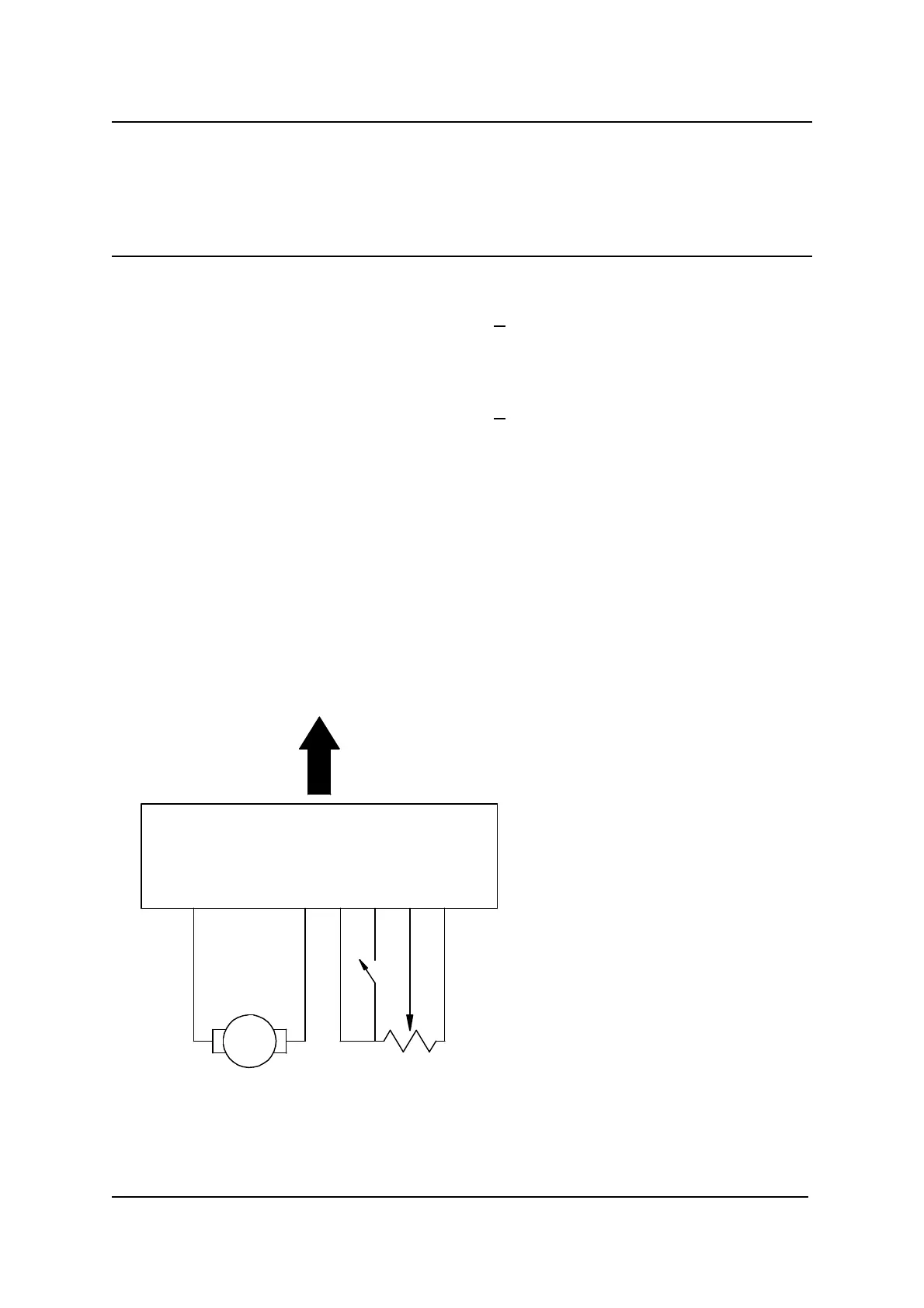
AMP Mate - N - Lok Connector
(AMP P/N 1-480-704-0)
1 4 2 65 3
Clutch
5 - 10 K
pot-
position
sense
Ω
Servo
steering
motor
To SLM Servo Connector
Wire Sizes
The minimum wire sizes that must be used are :
Function Wire Size (minimum) Terminal Part
Motor - 1.0 mm² motors < 10 A *
2.0 mm² motors > 10 A *
Common Ground 0.5 mm² AMP 350690
Position Sense Pot + 0.5 mm² AMP 350690
Motor + 1.0 mm² motors < 10 A *
2.0 mm² motors > 10 A *
Clutch Switch 0.5 mm² AMP 350690
Position Sense Pot Wiper 0.5 mm² AMP 350690
* AMP Split pin or Solid pin part numbers given above.
5.5.3 SLM Connection to Servo Devices
When the steering wheels are centred, there should be equal resistance between the
Position Sense Pot wiper and each end of the pot. Small differences can be
overcome during calibration (refer to the Programming section).
The motor wiring should be
such that when pin 4 is positive
with respect to pin 1, the servo
motor turns the pot so that the
pot wiper (pin 6) is driven
towards pot + (pin 3).