Machine description
ICC1300-1EN3.pdf2011-10-10
Electrical system
Fuses
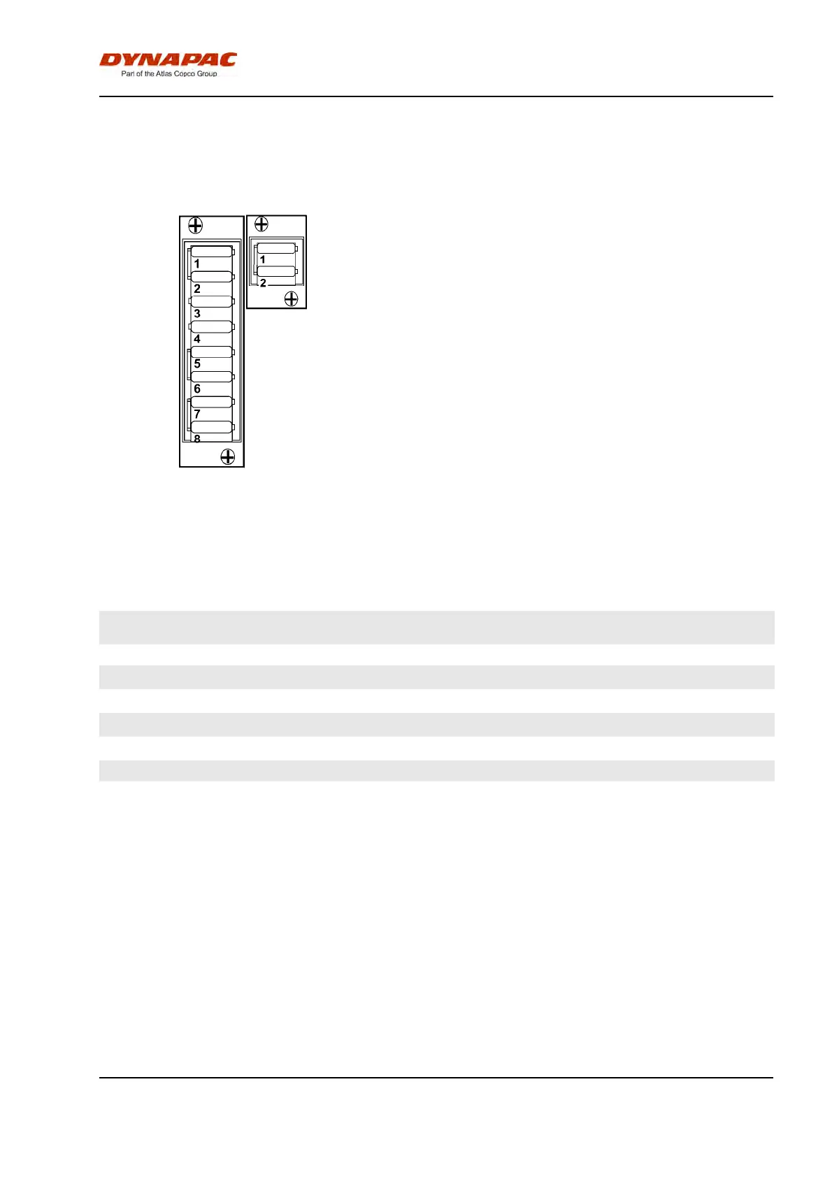
Fig. Fuse boxes
1. Upper
2. Lower
1
2
The figure shows the position of the fuses.
The table below gives fuse amperage and function. All
fuses are flat pin fuses.
Fuse box, Upper Fuse box, LowerFuse box, Upper Fuse box, Lower
1. ECU, Interlock, Instrument panel,
Sprinkler front, Vibration
10A 1. Reserve
1. ECU, Interlock, Instrument panel,
Sprinkler front, Vibration
10A 1. Reserve
2. Alternator, Horn, Fuel pump 10A 2. Flow divider 10A2. Alternator, Horn, Fuel pump 10A 2. Flow divider 10A
3. Indicators left 5A3. Indicators left 5A
4. Indicators right 5A4. Indicators right 5A
5. Hazard beacon 10A5. Hazard beacon 10A
6. Indicator relay, Power socket 12V 10A6. Indicator relay, Power socket 12V 10A
7. Position lights, Working lights front 15A7. Position lights, Working lights front 15A
8. Traffic lights, Working lights rear 15A8. Traffic lights, Working lights rear 15A
31