1290 Strain Gage Input Indicator 11
4. SETUP
4.1 FRONT PANEL
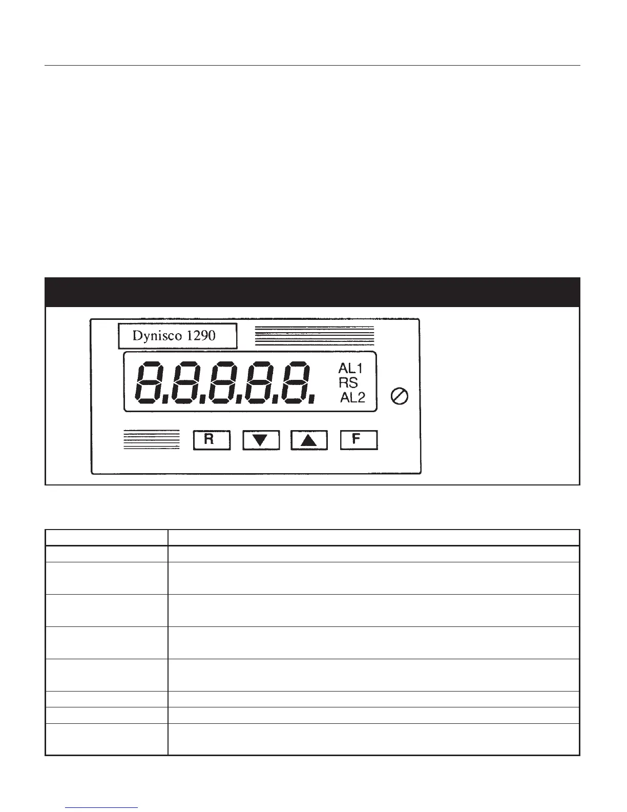
The front of the Model 1290 is shown in Figure 3. Key items on the front panel are:
•A five digit LED display
• LED indicators AL1 (Alarm 1) and AL2 (Alarm 2)
• LED indicator RS (Remote Status)
•Four pushbuttons protected by silicone rubber, labeled R, ▼, ▲, F. The pushbutton functions are
listed in the table below.
Fig. 3 Front Panel
4.2 PUSHBUTTON FUNCTIONS
Button Sequence Resulting Operation
▼ Used to step between choices or to decrement a parameter value
▲ Used to step between choices, increment a parameter value or to
display peak high or peak low
F Used to store currently displayed parameter value,
as modified, and to display the next parameter
R Used to scroll back to the previous parameter without storing the
modified parameter value
R + ▼ or Alarm manual reset (either button sequence will
R + ▲ reset both alarms)
R + F Reset peak high and peak low values
▼ + ▲ Initiate default data loading procedure
▼ + R + F Used to lock or unlock keyboard for transducer calibration
and parameter modification