14
Fig. 5 Front Panel and Circuit Board Assembly
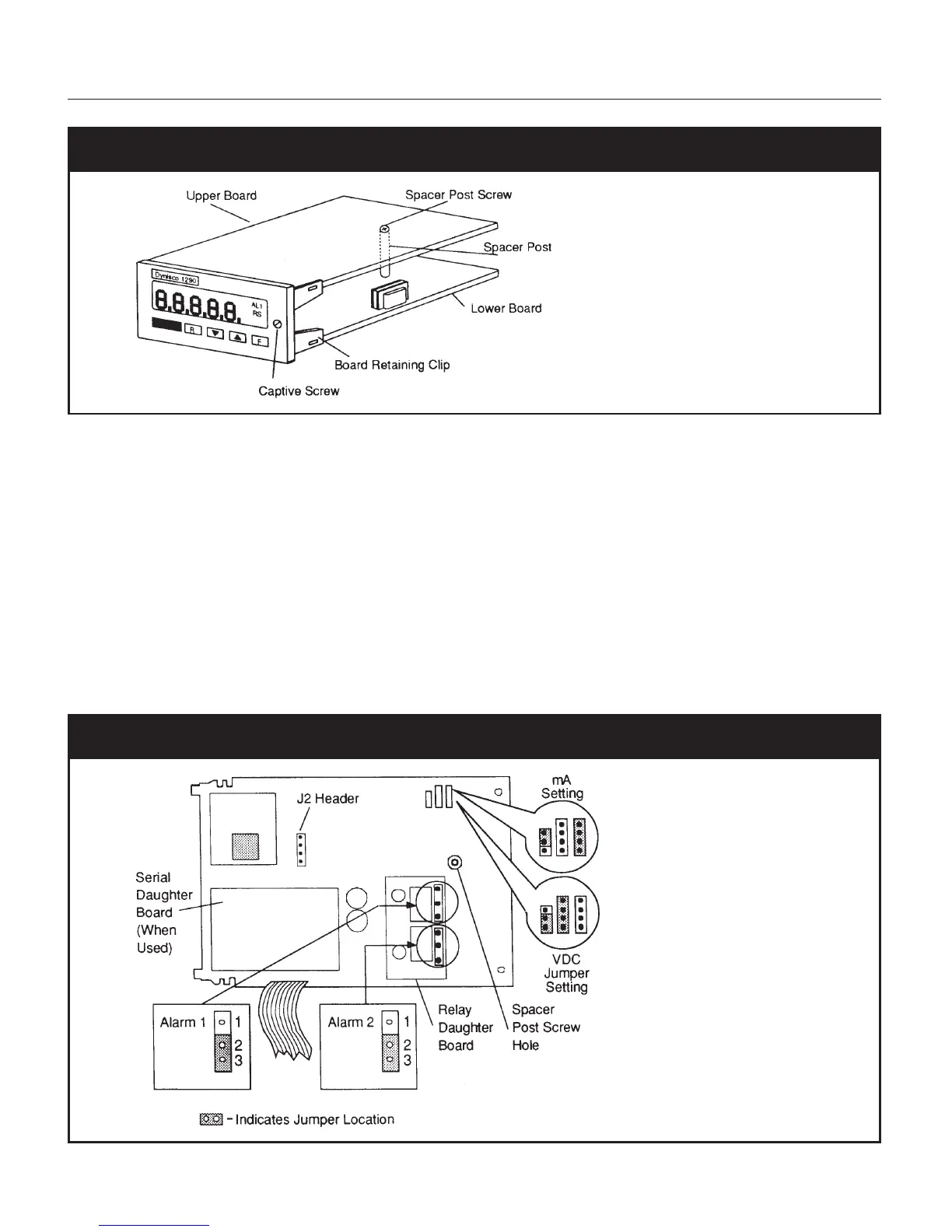
4.5.2 OUTPUT JUMPER SETTINGS
Output options are selected by the placement of jumpers on the upper circuit board. The choices
available are:
•Voltage or current loop output for analog retransmission. Jumper setups are shown in Figure 6.
The default selection is a 4-20 mA current output, with alarm outputs normally closed.
•The alarm jumpers (normally open or normally closed) are shown in Figure 6 and described in
the table on the next page. Each alarm is configured independently.
CAUTION: Wear an anti-static wristband and work on an anti-static surface when setting jumpers.
Fig. 6 Upper Circuit Board and Jumper Settings