12
To perform operations requiring two or more pushbuttons, press and hold the first pushbutton then
press and hold the second pushbutton, and then press the third pushbutton, if required.
NOTE: You must follow the pushbutton sequences exactly as described.
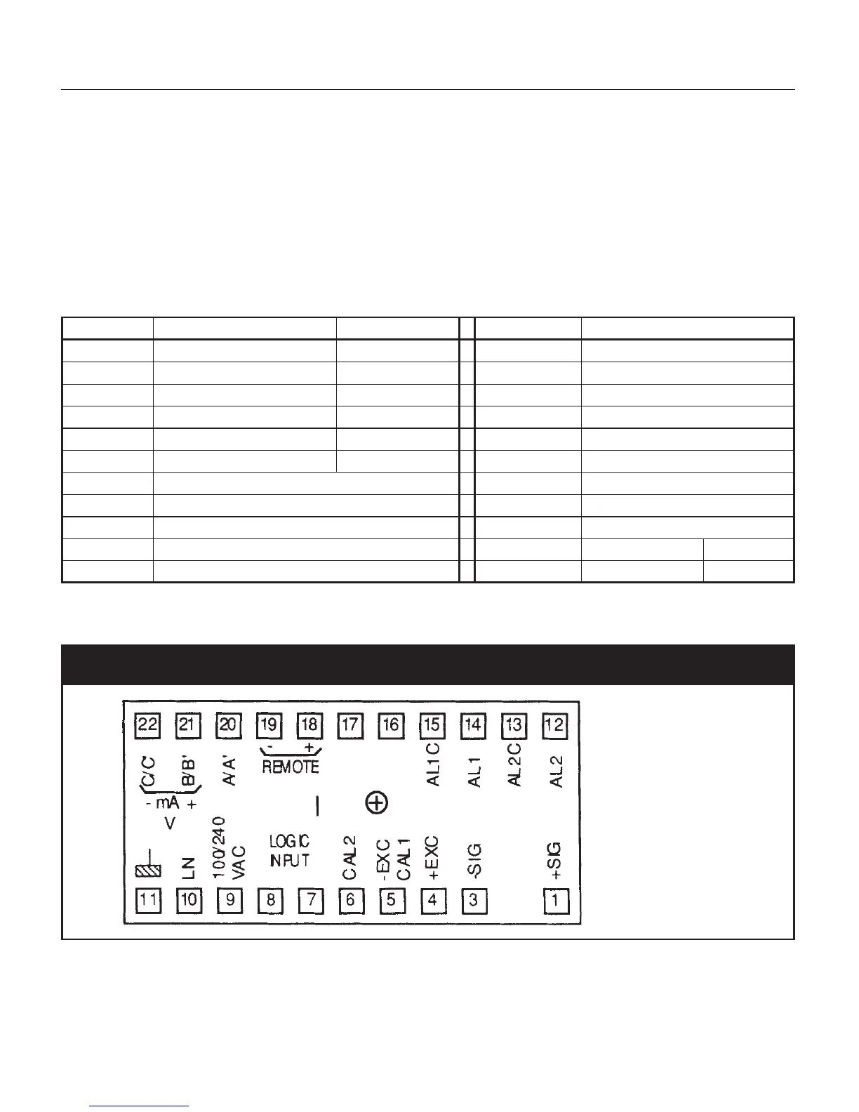
4.3 REAR TERMINAL CONNECTIONS
The electrical connections for the Model 1290 are shown in the table below. The layout of the
terminals, as seen from the rear, is shown in Figure 4.
Terminal Connection Dynisco Wire Terminal Connection
1 Signal + Red 12 Alarm 2
(no terminal) 13 Alarm 2C
3 Signal — Black 14 Alarm 1
4+ Excitation White 15 Alarm 1C
5— Excitation/ CAL1 Green + Blue 16 N/C
6CAL 2 Orange 17 N/C
7 Logic Input 18 Remote Enable
8 Logic Input 19 Remote Enable
9 Line (Hot side) VAC, or +24 VDC 20 A/A’
10 Line (Neutral), or 0 VDC 21 Output V/mA+ B/B’
11 Ground 22 Output V/mA- C/C’
NOTE: Do not connect any wires to terminals 16 and 17.
Fig. 4 Rear Terminal Locations
4.4 INPUT WIRING
Connect the pressure transducer per the instructions detailed below. Do not run input wires in the