1290 Strain Gage Input Indicator 13
same bundle with power cables; instead, shielded cable should be used and grounded at the
transducer end only (Dynisco’s cable assembly provides this grounding).
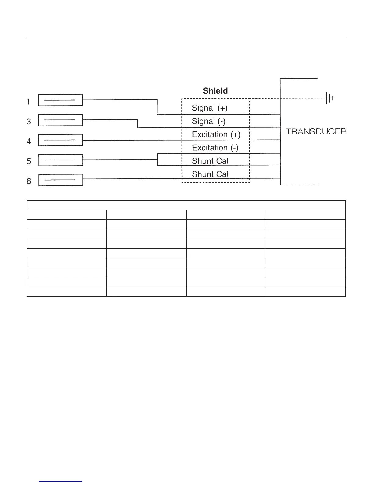
Dynisco Standard Wire Code Transducer Pin-Out
Lead Color PT420 Series PT460 Series
Excitation + White A C
Signal + Red B A
Excitation - Green C D
Signal - Black D B
Calibration Blue E E
Calibration Orange F F
G (unused)
H (unused)
4.5 INTERNAL SETTINGS
The indicator consists of an upper and a lower printed circuit board and a front panel. These are
connected by ribbon cables which are soldered in place.
CAUTION: Be careful not to twist the ribbon cables during assembly and disassembly.
4.5.1 DISASSEMBLY
1. With a small slotted screwdriver, loosen the captive screw on the right side of the front panel.
2. Slide out the front panel and printed circuit board assembly, and place it on a flat, anti-static
work surface. Notice that the circuit boards are held in place by four plastic clips. See Figure 5.