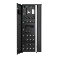
7. Route and connect power wiring. Use movable cable support beams if
needed. See Figure 15: Cable support beams.
8. When all wiring is complete, close the right panel and tighten the screws.
9. If installing a parallel system, repeat the above steps to all units in the
system.
Figure 13: Removing the right panel
Figure 14: Gland plate locations
1. Top exhaust fan panel
(optional)
© Eaton Corporation plc 2020. All rights reserved. Revision: 001 Document ID: P-164000956 58 (141)
Eaton 93PM G2 UPS 50 – 360 kVA User’s and Installation Guide

 Loading...