Eaton 93PM UPS 480V Three-Wire – 100 kW Frame Installation and Operation Manual 164000227—Rev 07 ix
LLiisstt ooff FFiigguurreess
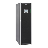
Figure 1. Eaton 93PM UPS – 100 kW Frame ....................................................................................................2
Figure 2. Eaton 93PM UPS –100 kW Frame with Left or Right-Mounted Sidecar ...................................................... 2
Figure 3. UPS Cabinet Dimensions (Front and Right Side Views)......................................................................... 17
Figure 4. UPS Cabinet Dimensions (Top and Bottom Views) .............................................................................. 18
Figure 5. UPS Cabinet Front and Back Floor Mounting Bracket Mounting Dimensions (Back Views) ........................... 19
Figure 6. UPS Cabinet with Left or Right-Mounted Sidecar Dimensions (Front Views) ............................................. 20
Figure 7. UPS Cabinet with Left or Right-Mounted Sidecar Dimensions (Top and Bottom Views) ............................... 21
Figure 8. UPS Cabinet Center of Gravity ........................................................................................................ 22
Figure 9. UPS Cabinet with Left or Right-Mounted Sidecar Center of Gravity ......................................................... 23
Figure 10. Remote EPO Switch Dimensions .................................................................................................... 24
Figure 11. 93PM External Parallel Wire Length ................................................................................................. 26
Figure 12. UPS Cabinet as Shipped on Pallet .................................................................................................... 38
Figure 13. UPS Cabinet with Left-Mounted or Right-Mounted Sidecar as Shipped on Pallet........................................ 38
Figure 14. Removing the Pallet Skids and Supports – Eaton 93PM UPS ................................................................. 40
Figure 15. Removing the Sidecar Pallet Skids and Supports – Eaton 93PM UPS....................................................... 41
Figure 16. Removing the Sidecar Rear Shipping Bracket – Eaton 93PM UPS .......................................................... 43
Figure 17. UPS Conduit and Wire Entry Locations ............................................................................................. 46
Figure 18. Sidecar Conduit and Wire Entry Locations ......................................................................................... 47
Figure 19. UPS Inter-Cabinet Wiring Access Location......................................................................................... 48
Figure 20. Power Terminal Locations.............................................................................................................. 49
Figure 21. Power Terminal Detail ................................................................................................................... 50
Figure 22. Interface Terminal Locations........................................................................................................... 52
Figure 23. Interface Terminal Detail................................................................................................................ 52
Figure 24. Bottom Access Interface Wiring Location.......................................................................................... 53
Figure 25. Wire Tie Anchors ......................................................................................................................... 54
Figure 26. Building Alarm Terminal Block Connector Assignments ........................................................................ 55
Figure 27. Relay Contact Terminal Block Connector Assignments......................................................................... 55
Figure 28. Battery Shunt Trip Location ............................................................................................................ 58
Figure 29. Battery Shunt Trip Terminal Detail.................................................................................................... 59
Figure 30. Battery Shunt Trip Terminal Assignments.......................................................................................... 60
Figure 31. External Parallel CAN Wiring........................................................................................................... 63
Figure 32. External Parallel Terminal Block....................................................................................................... 63
Figure 33. External Parallel Pull Chain Wiring .................................................................................................... 65
Figure 34. REPO Switch .............................................................................................................................. 68
Figure 35. REPO Terminal Block Connector Assignments ................................................................................... 69
Figure 36. Normally-Open REPO Switch Wiring ................................................................................................ 69
Figure 37. Normally-Closed REPO Switch Wiring .............................................................................................. 70
Figure 38. Main Elements of the UPS System .................................................................................................. 73
Figure 39. Path of Current Through the UPS in Energy Saver System Mode............................................................ 75

 Loading...