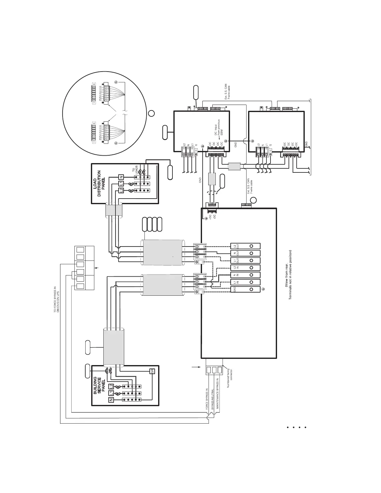
Figure 35. Wiring Diagram - UPS with No External Bypass (L1, L2, N)
1
2
3
5
6
3
2
4
6
110/220 Input, 110/220 Output
120/208 Input, 120/208 Output
120/240 Input, 120/240 Output
127/220 Input, 127/220 Output
INPUT / OUTPUT
POWER BUS BAR
CN13
UPS NO AUX NO AUX NC
3
2
1
INPUT FROM
FACILITY
EXTERNAL
DC
AC
OUTPUT
AC
INPUT
UPS
UPS INPUT
SIGNALS
CN3
CN4
CN6
CN6
CN4
5
6
AC INPUT
TO EBM 1
AC INPUT
TO EBM 2
TO NEXT EBM
(If installed)
DC
INPUT
EBM 1
}
EBM 2
CN3
CN4
CN3
CN4
7
A
A
G
L2L1 N
G
L2
L1
N
7 6 5 4 3 2 1* 7 6 5 4 3 2 1
UPS
CN4
EBM
CN4
Supplied
Connectors
*Pin numbering
is right-to-left
Input Signal connections
(Typical)
8

 Loading...


