Installation i-on16
Page 12
To Leave Local Programming Mode and
Save Changes
EITHER:
Press
OR
Close the keypad tamper.
The keypad saves the changes you have made in
its local memory.
You can now remove 12Vdc power, if required, or
leave Installer Menu on the control unit.
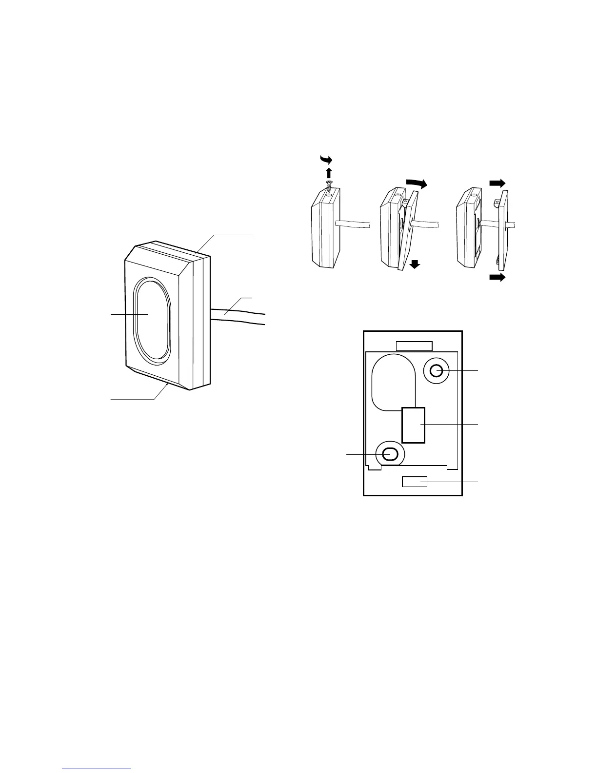
KEY-EP External Prox Reader
Figure 20 shows the outside details of the external
prox reader KEY-EP:
1. LED window.
2. Retaining Screw.
3. Removable Fixing Plate.
4. Permanently attached cable.
Figure
External Prox Reader KEY-EP
Siting the External Prox Reader
Do site the External Prox Reader:
At a convenient height and location for the user.
Out of sight of potential intruders.
Note that the external prox reader is fitted with a
length of 2m of the appropriate cable. The cable
can be extended up to 50m by connecting an
additional length of 7/0.2 un-screened alarm
cable.
Do NOT site the External Prox Reader:
Next to electronic equipment, particularly
computers, photocopiers or other radio
equipment, CAT 5 data lines or industrial mains
equipment.
Note: Do not site the external prox reader closer
than one meter to any other kind of prox reader (for
example an i-kp01, KEY-KP01/KPZ01 or another
external prox reader). If you do so then the prox
readers will interfere and be unable to read tags.
Opening the External Prox Reader
To open the external prox reader (see Figure 21):
1. Undo the single retaining screw.
2. Tilt the edge of the fixing plate and then slide it
a short distance parallel to the body of the prox
reader.
3. Slide the fixing plate away from the reader
body, along the cable.
Figure
External Prox Reader Fixing Plate
Fit External Prox Reader
Use M4 25mm countersunk screws at both fixing
holes when mounting the back of the keypad on the
wall. Ensure the screw has a thread suitable for the
wall material.
Connecting Remote Prox Reader to
Keypad
Segregate the external prox reader cable from any
other wiring such as mains supply cables,
telephone cables, computer network cables and
R.F. cables. Use cable ties to keep cables
separated.

 Loading...


