Installation
Copyright © 2008-2010 Eaton Corporation. All Rights Reserved.
IPN 997-00012-68D February 2010
11
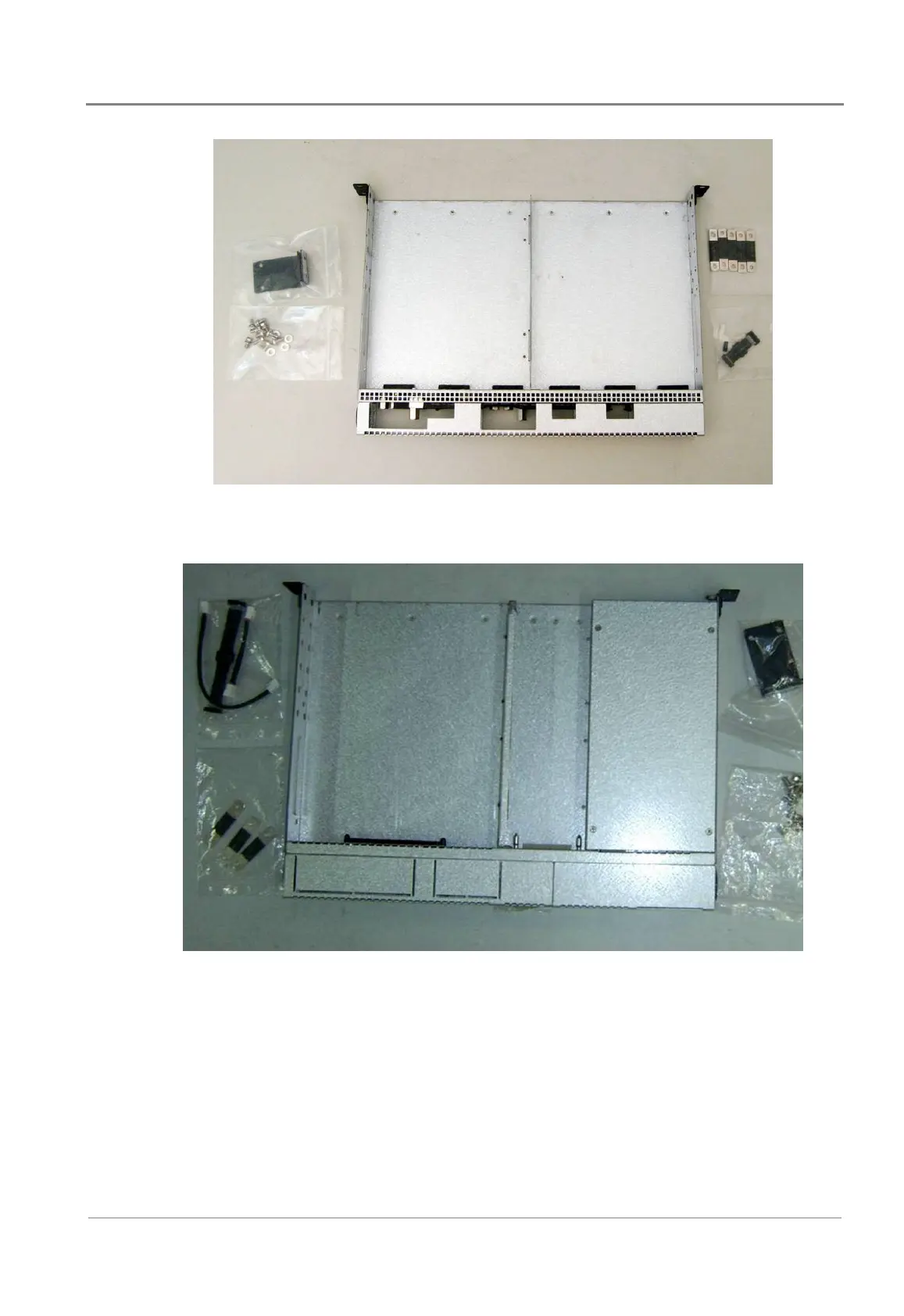
Inverter Chassis
Includes: 23" rack mount brackets (2), interconnection bus bars (5), busbar screws (8),
mounting screws (4), communications cable (1), jumper (1)
50A STS/controller/interface Chassis
Includes: 23" rack mount brackets (2), interconnection bus bars (3), busbar screws (8),
mounting screws (4), CAN cable for controller (1), DC power cable for controller (1),
communications cable (1), 4-pin jumper (for CN1 if BMS is not used)
 Loading...


