Installation
Copyright © 2008-2010 Eaton Corporation. All Rights Reserved.
IPN 997-00012-68D February 2010
19
Task 5 - Multi-Shelf Wiring Option
Ignore this Task if the system has only one inverter chassis.
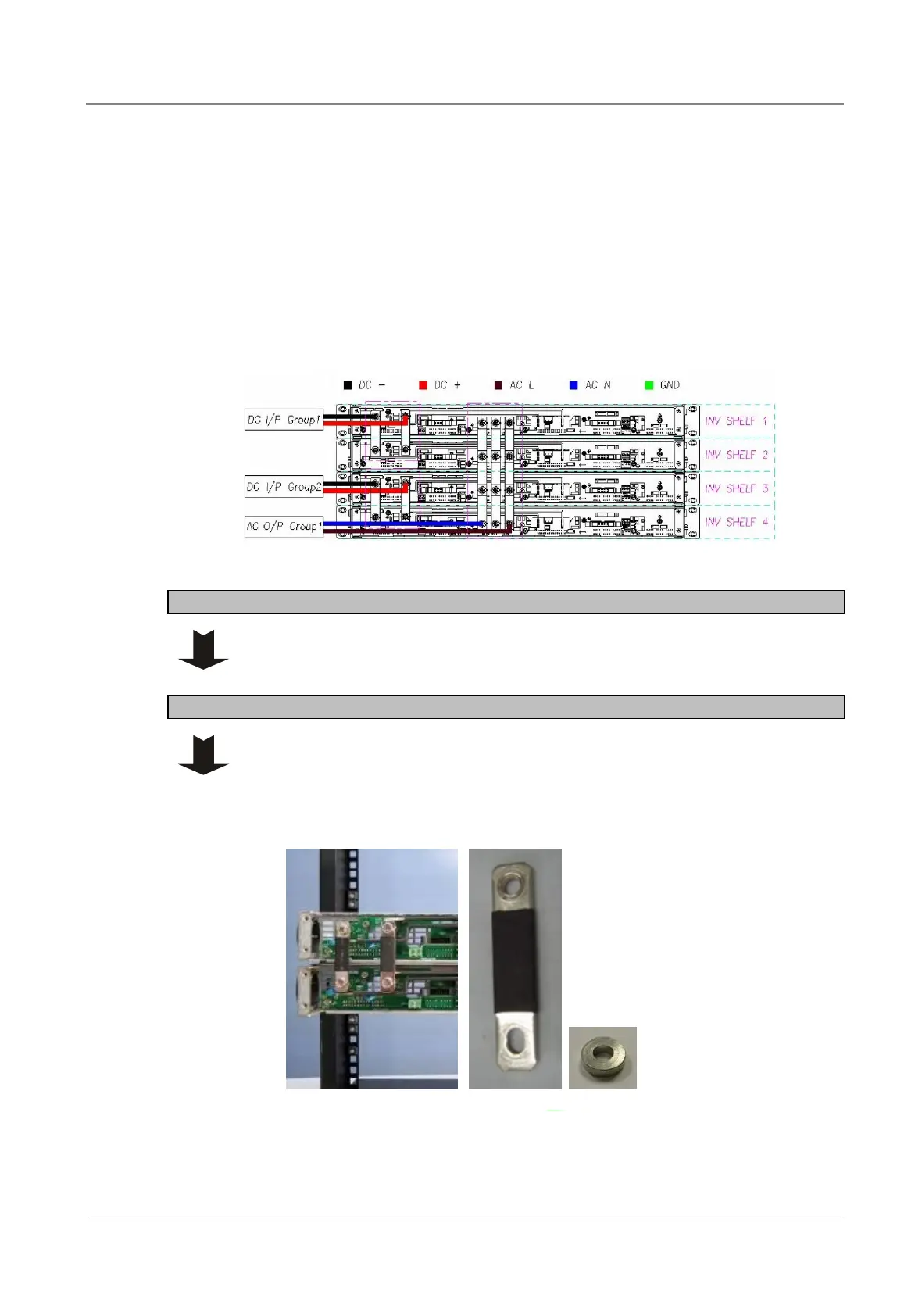
Group Connection
The dc input current to the inverters must not exceed the current limit of dc cables. If the total
input current of all inverters exceeds the cable current limit, split the inverters into groups and
choose suitable wire size for each group.
For example:
An inverter system with eight 1000VA/48Vdc/120Vac inverter modules (8kVA). The total
input current is 151.5A. Connect the inverters in two groups of four using the with separate
dc cables to each group (75.8A each) as shown.
Step 1 - Remove inverter shelf rear cover
Step 2 - Connect dc input
When necessary, use the spacers provided to keep the bars vertical.
1 Use the bars provided to connect together all the dc negative input (BAT-)
studs for each group of inverters (see Group Connection above).
2 Use the bars provided to connect together all the dc positive input (BAT+)
studs for each group of inverters (see Group Connection above).
3 Refer to the Wire Size Tables on page 16
and local wiring rules, and select
the correct size dc input cable for the current and cable length, for each
group of inverters.
 Loading...


