Installation
Copyright © 2008-2010 Eaton Corporation. All Rights Reserved.
IPN 997-00012-68D February 2010
15
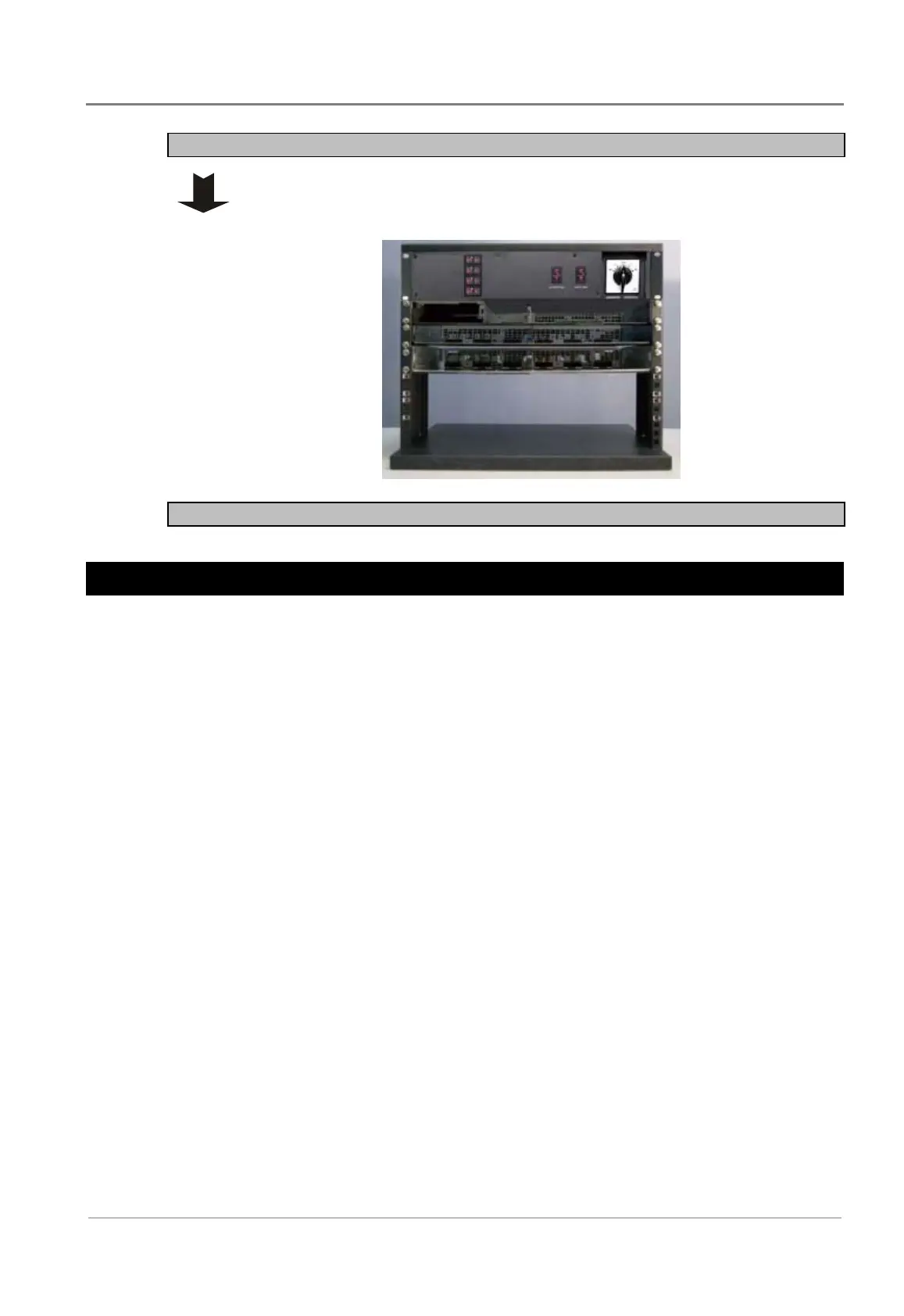
Step 2 - Mount chassis
1 Fit the MBS/PDU chassis (either 50A or 100A) to the equipment rack, and
align holes of mounting brackets and rack.
2 Secure the chassis with the four screws provided.
Procedure complete
Wiring Connection
CAUTION: Ensure all the power sources are OFF during wiring. Disconnect battery cables
from battery.
The inverter modules are designed to operate in parallel for higher output current, two modules
are automatically connected in parallel in each shelf. Two or more inverter shelves can be
further connected in parallel for additional output power. This is done by connecting all inputs
(BAT-, BAT+) in parallel, and outputs (Line, Neutral and Ground) in parallel. When paralleled
there is no master unit and each unit adjusts its own power level for best power sharing. Please
refer to the following wiring instructions for your needs.
When selecting wiring, consider the following factors:
• Current carrying capacity of the wire
• Maximum wire length needed
• Maximum ambient temperature
 Loading...


