Installation
Copyright © 2008-2010 Eaton Corporation. All Rights Reserved.
IPN 997-00012-68D February 2010
23
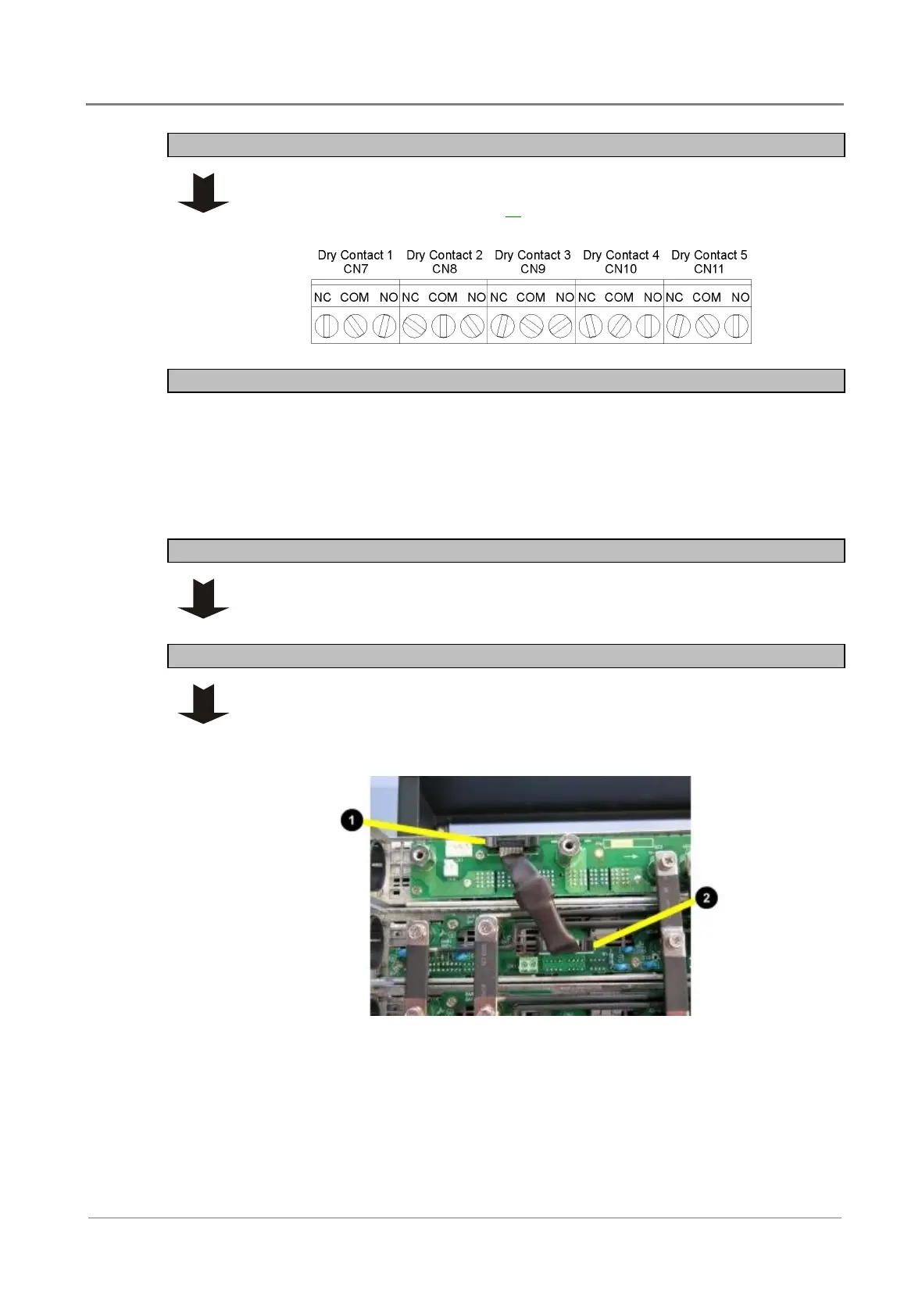
Step 4 - Dry contact connections
Use #30~16 AWG to connect to the relay dry contacts.
Refer to Alarm Settings on page 38 to set the alarm mode of the dry contacts.
Procedure complete
Task 7 - Connect STS (if used)
CAUTION: Shut down all the power sources and disconnect battery cables from battery before
wiring.
Step 1 - Remove STS rear cover
Step 2 - Connect STS signal cable
Connect the supplied STS signal cable from the rear panel of STS Shelf to the
rear panel of the inverter shelf. Either:
• For 50A STS Module: connect from CN2 on STS to CN7 on inverter.
"
Parallel signal port (CN2) on the 50A STS
shelf backplane
#
Parallel signal port (CN7) on inverter shelf
backplane
 Loading...


