Matrix Telecom Inverter System
24
Copyright © 2008-2010 Eaton Corporation. All Rights Reserved.
IPN 997-00012-68D February 2010
• For 100A STS Module: connect from CN11 on STS to CN7 on inverter.
"
Parallel signal port
(CN11) on 100A STS
shelf backplane
#
Parallel signal port
(CN7) on inverter shelf
backplane
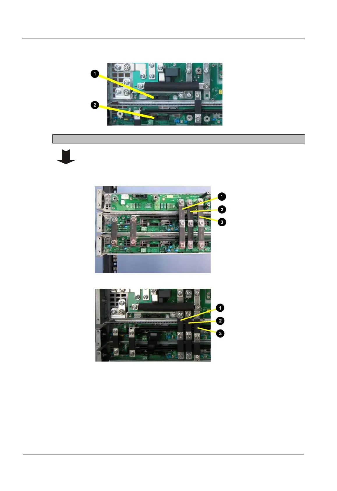
Step 3 - Install AC bus bar between STS and Inverter
When necessary, use the spacers provided to keep the bars vertical.
Connect AC BUS of the Controller/Interface/STS shelf to the AC BUS
connector of the top inverter:
• 50A STS Module:
"
AC neutral (UC3)
#
Earth (UC1)
$
Inverter AC Line
• 100A STS Module:
"
AC neutral
#
Earth
$
Inverter AC Line
 Loading...


