Installation
Copyright © 2008-2010 Eaton Corporation. All Rights Reserved.
IPN 997-00012-68D February 2010
17
Notes:
1 Total Power Rating (VA, W) = No. of shelf × Inverter module power rating (VA, W) * 2
2 I/P current = Total power rating (W) ÷ 0.87 ÷ 40
3 O/P current = Total power rating (VA) ÷ AC voltage.
Task 4 - Single-Shelf Wiring Option
Ignore this Task if the system has more than one inverter chassis.
Step 1 - Remove inverter shelf rear cover
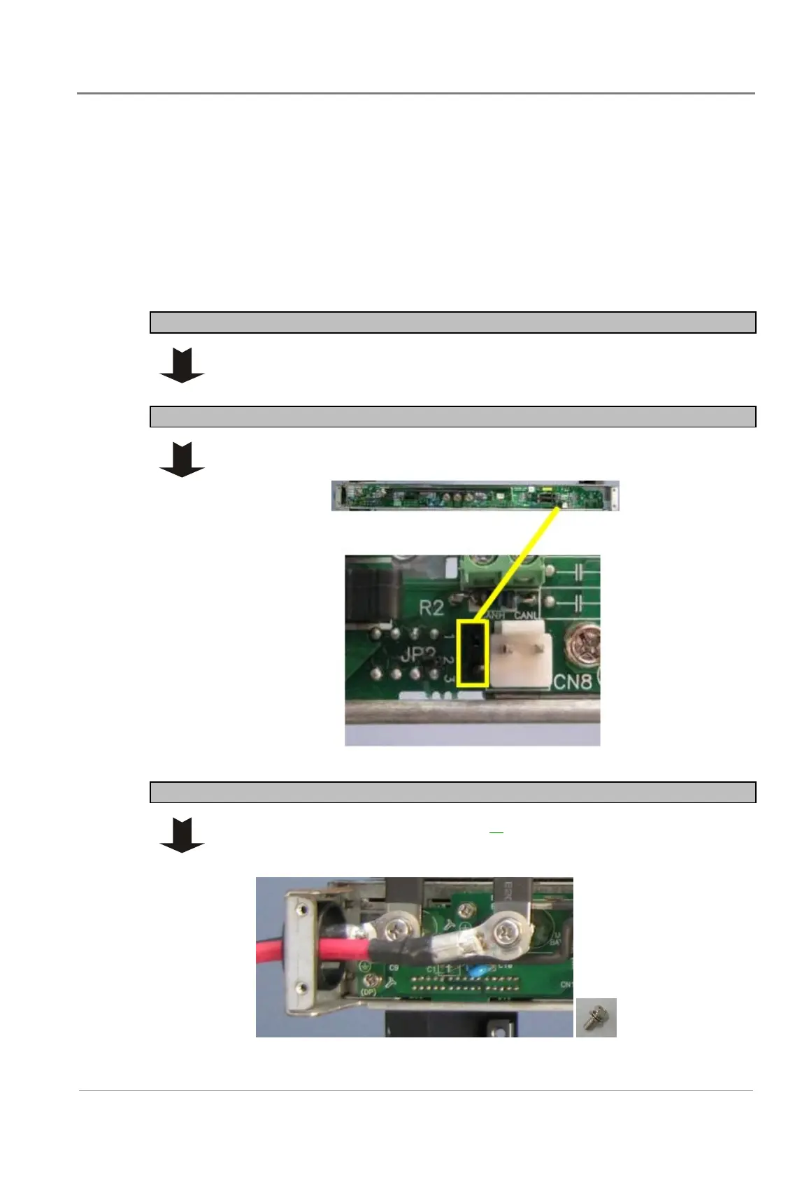
Step 2 - Insert JP2 jumper
For single-shelf systems only, insert the jumper supplied from PIN 1 - 2 of
connector JP2.
Step 3 - Connect dc input
1 Refer to the Wire Size Tables on page 16
and local wiring rules, and select
the correct size dc input cable for the current and cable length.
2 Terminate the cables with M4 crimp lugs.
 Loading...


