Installation
Copyright © 2008-2010 Eaton Corporation. All Rights Reserved.
IPN 997-00012-68D February 2010
29
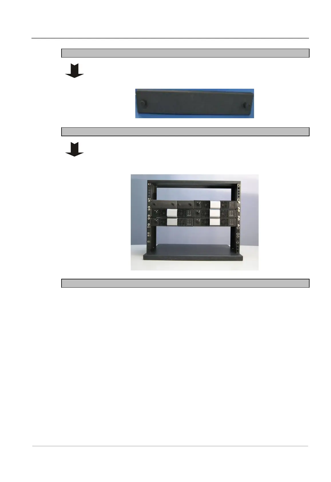
Step 3 - Cover any unused inverter positions
Cover any unused positions with the optional cover plate as follows.
The cover plate is two pieces: Screw the inner silver metal piece to the chassis
bottom plate. Use bolts to attach the black metal cover to the inner silver piece.
Step 4 - Cover controller and/or interface position
If the controller module and/or interface module is not fitted, cover the
positions with the optional cover plates.
The cover plate is two pieces: Screw the inner silver metal piece to the chassis
bottom plate. Use bolts to attach the black metal cover to the inner silver piece.
Procedure complete
 Loading...


