EasyManuals Logo

Eaton Sefelec RXS500 User Manual

Eaton Sefelec RXS500
156 pages
To Next Page IconTo Next Page
To Previous Page IconTo Previous Page
Page #94 background imageLoading...
Page #94 background image
XS series operating manual
XS user manual v0.55 - 93 -
Connections
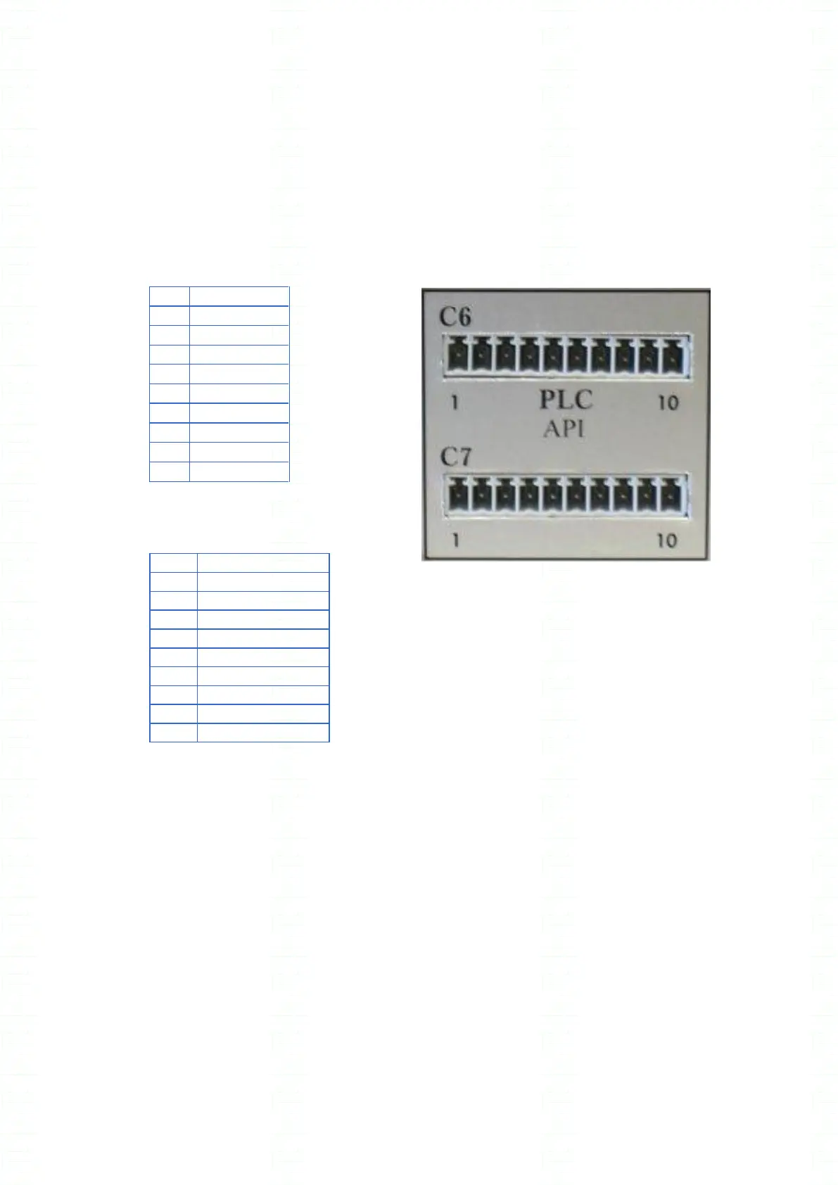
The Input Output signals are available on the unit rear panel on screw terminals C6 and C7.
Warning : each screw terminal has a key to avoid wrong connection.
Connector C6
Connector C7
1
TYPE
2
MESDCH
3
DTR
(2)
4
COMOUT
5
CTRLOUT
6
PLCFAIL
7
EOT
8
PLCPASS
9
ERROR
10
GND
(1)
Internal 25VDC power supply none regulated and protected by Polyswitch fuse with a maximum
current of 1A. If the Polyswitch breaks the circuit in case of over current, please reduce the external
current consumption and wait for a few minutes before trying again
(2)
DTR input: not used in the XS series. Don’t connect any signal on that pin.
1
IN010V
2
OUT010V
3
GND10V
4
+25V
(1)
5
COMIN
6
CTRLIN
7
N0
8
N1
9
N2
10
N3
Fig 12.1

Table of Contents

Questions and Answers:

Question and Answer IconNeed help?

Do you have a question about the Eaton Sefelec RXS500 and is the answer not in the manual?

Eaton Sefelec RXS500 Specifications

General IconGeneral
BrandEaton
ModelSefelec RXS500
CategoryTest Equipment
LanguageEnglish

Related product manuals