P.26
PM10U
EBARA
CORPORATION
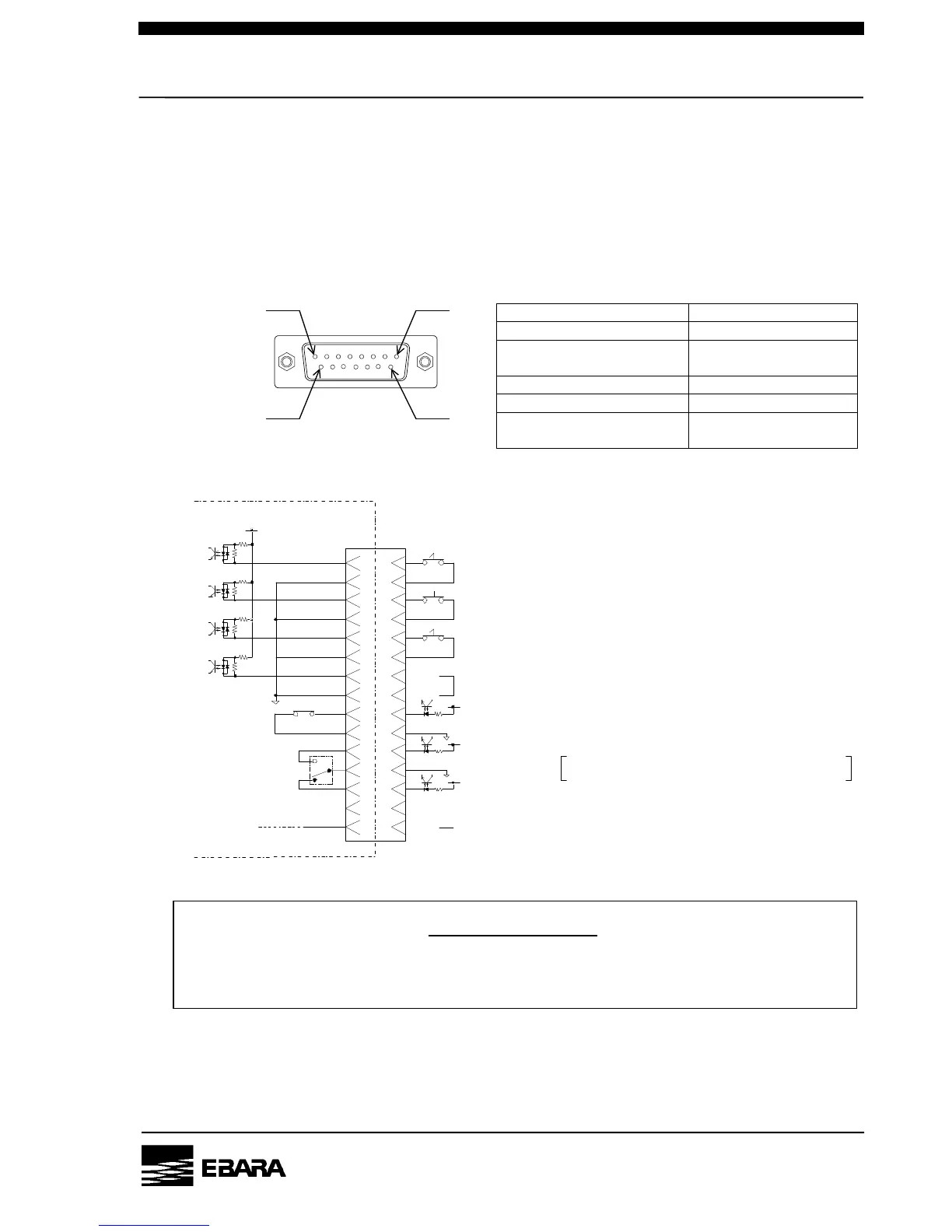
4.3.2 Control wiring (Connector symbol: I/O connector CN2)
Please install the driving connector in the I/O connector (CN2) when it will operate under “Direct power
input”.
To perform remote operation or monitoring, perform wiring to the I/O connector CN2.
For pin connections, refer to Fig.4.5, 4.6 and Table4.7.
Table 4.7 CN2 Receptacle Specification
D-sub model DA-15SF-N
Fixed screw (D20418-J3F) M2.6
Connector maker
Japan Aviation
Electronics Ind., Ltd.
Applicable plug (Note) DA-15PF-N
Clamp hood (Note) DA-C8-J10-F1-1
Fig.4.5 CN2 Pump-side Receptacle
Applicable wire size
AWG #24-20
(0.2-0.5mm
2
)
Note) Applicable plug and clump hood are not attached.
Please prepare by the equipment side.
Fig.4.6 I/O connector CN2 D-sub Connector Pin connections
CONFIRMATION
For Input signals (Pin No. 1-9, 2-10, 3-11, 4-12), apply a voltage of 24V DC on the pump
controller side. Don't apply a voltage on the equipment side; otherwise the controller may go
wrong.
8
15
1
9
DP RUN Input (CLOSED : RUN)
88
15 15
77
14 14
66
13 13
55
12 12
44
11 11
33
10 10
22
99
11
RESET Input (CLOSED : RESET)
LOCAL/REMOTE Selection switch (CLOSED : REMOTE)
ALARM Status
N.C
DC24V
4.7kΩ
CLOSED (NO contact ; PIN 6-14) : ALARM
OPENED (NC contact ; PIN 7-14) : ALARM
DP RUN Status (CLOSED : RUN)
DC24V
For Service
Preliminary input
Pump Control Box
The conection disabled
N.C