EC-PM-80320 Service Manual
- 10 -
CLK Frequency f CLK -- -- 8 MHz
CLK Pulse Width tw CLK
Refer to Timing signal
figure
35 -- -- ns
DAT Start-up Time setup DI
Refer to Timing signal
figure
30 -- -- ns
DAT Holding Time thold DI
Refer to Timing signal
figure
10 -- -- ns
DAT Output Delay td DO
Refer to Timing signal
figure
-- -- 120 ns
LATCH Pulse Width tw LAT
Refer to Timing signal
figure
100 -- -- ns
LATCH Action Time
tsetup
LAT
Refer to Timing signal
figure
200 -- -- ns
LATC Holding Time thold LAT
Refer to Timing signal
figure
50 -- -- ns
DST Start-up Time
tsetup
DST
Refer to Timing signal
figure
300 -- -- ns
Output Delay Time tDo
Refer to Timing signal
figure
-- -- 5 ns
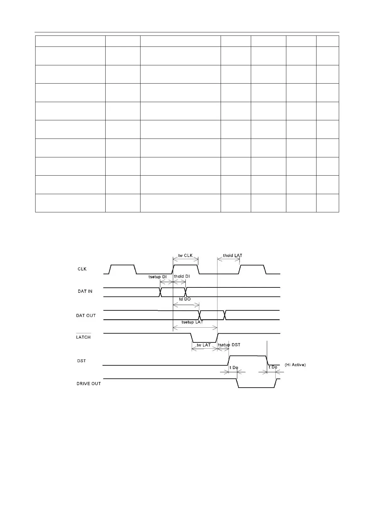
4.1.5 Timing Signal Figure
4.1.6 Thermal Head Resistance
The resistance of EC-PM-80320 thermal head is about 630.5 to 669.5Ω.
4.1.7 Thermal Head Voltage
There is a drive IC inside the printer, whose drive voltage is from 21.6 to 26.4V and logical voltage
is from 4.75 to 5.25V.
4.2 Sensor
Table4-2 Electric character of Thermal head
Figure 4-5 Timing Signal Figure
 Loading...