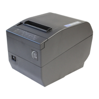
EC-PM-80320 Service Manual
- 14 -
4.3.2 Part’s Main Function
1. Power supply Adapter
Supply +24V DC
2. Main-Board
Take charge of the whole printer. If the main-board is electrified working properly, the power
LED in control panel lights for a long time and other two LEDs blink once when the printer is
turned on. The parts controlling the printer are made up of CPU, SDRAM, DATAFLASH and
Drive electric circuit etc.
(1)CPU
AT91SAM7SE32 is a 32-bit microprocessor based on ARM7.
(2)DATAFLASH
The size of it is 4MB and it is used to store Chinese big word-database, ASCII characters
and program.
(3)SDRAM
8MB, all the program runs in the SDRAM.
(4)Paper Feed Motor Driver
Control the paper-motor.
(5)Cutter Driver
Control the cutter motor.
(6)Power supply IC2360AD
Support +5V power supply. The system key parts are working at +5V except CPLD.
3. Control panel
The control panel is used to display printer’s working condition and Paper feed function, which
is made up of a switch and three LEDs.
4. Motor
The printer’s motor contains Slice paper motor and Paper-feed motor, whose drive voltage is
24V.
5. Thermal Print Head
The thermal piece is made up of 640 fever components, 576 of which in the middle are
available.
6. Cash Drawer Interface
Connect the printer to cashbox through this interface.
7. Sensor
There are altogether four sensors except the print head module. Paper sensor, paper end
sensor are photo-electricity sensors, while paper-cutter sensor and print roller position sensor
are mechanical sensors.
8. Standard interface
The EC-PM-80320 printer is configured with a cash drawer interface and a data interface
(parallel interface, USB interface, USB interface + serial interface, USB interface + Ethernet
interface, USB interface + Bluetooth, USB interface + Wi-Fi).
4.3.3 Function of Interface
CN1: Eight-thread socket, specified for CPLD downloading program.
CN2: Nine-thread socket, which connects to paper sensor, shaft-press sensor and paper-feed
motor. (Shown as table 4-6)
CN3: Cash drawer interface.
CN4: Thread-socket of printer mechanism, connects thermal print head. (Shown as table 4-7)
 Loading...