Eclipse Rotary Actuator Instruction Manual 904-7/24/06
24
Note:
In the following examples:
1) 0°and 90° represent the actuator shaft’s range of travel rather than the
shaft’s alignment (therefore, 0° does not equal vertical and 90° does not
equal horizontal).
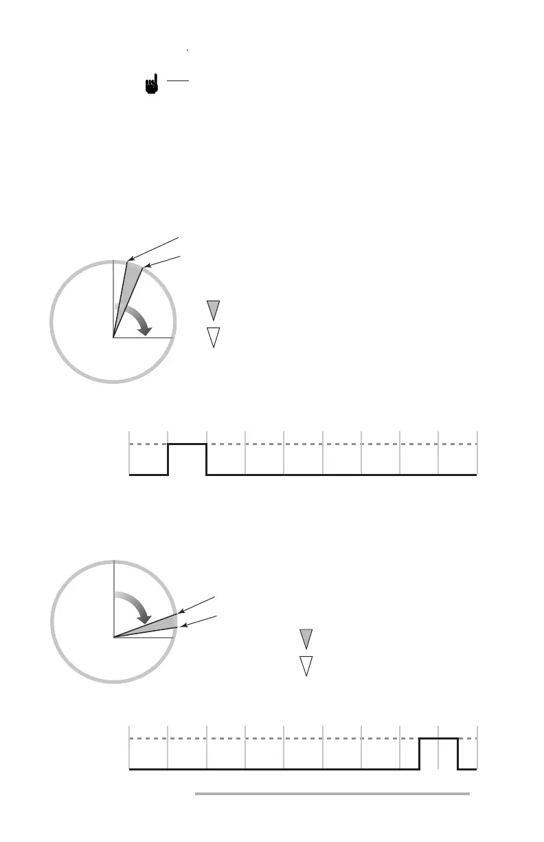
2) The operating mode is normally open, but the values LL, LS, HS and HH
have been changed from the default setpoints shown on page 29. The set
values are: LL=10, LS=20, HS=75 and HH=85
Figure 5 Auxiliary Contact Positions in Relation to Shaft Rotation
0
o
0
o
90
o
LL=10
o
LL
HS HH
LS
CLOSED
OPEN
Low Auxiliary Contact (P2-5 & 6)
Angular Diagram
Angular Diagram
Linear Diagram
Linear Diagram
10
o
20
o
30
o
40
o
50
o
60
o
70
o
80
o
90
o
0
o
CLOSED
Actuator Shaft’s Degree of Rotation
OPEN
High Auxiliary Contact (P2-3 & 4)
10
o
20
o
30
o
40
o
Actuator Shaft’s Degree of Rotation
50
o
60
o
70
o
80
o
90
o
A
c
t
u
a
t
o
r
S
h
a
f
t
LS=20
o
Key
Contact Closed
Contact Open
For the settings of note 2,
the low contact is closed
when the shaft is between
10 and 20 degrees.
0
o
90
o
HS=75
o
A
c
t
u
a
t
o
r
S
h
a
f
t
HH=85
o
Key
Contact Closed
Contact Open
For the settings of note 2,
the high contact is closed
when the shaft is between
75 and 85 degrees.