Eclipse Rotary Actuator Instruction Manual 904-7/24/06
17
A switch or voltage-free contact can be wired
between P1-4 (High FIRE) and P1-1 (COM) to
move the actuator to the high re position.
Note:
These digital signals override the 4-20mA and
0-10Vdc analog positioning signals.
Connect a 4-20mA signal positive (+) to P1-2 and
negative (–) to P1-1 (COM). Or alternately connect
a 0-10 Vdc signal positive (+) to P1-3 and negative
(–) to P1-1 (COM). If both signals are connected,
the greater value signal will determine the actuator’s
position.
After setting the parameters according to
Section 3, connect P1-6 (LC) to P1-1 (COM) to
prevent inadvertent parameter changes through
the keypad. With this jumper installed, pressing
the ENTER key will display "LC" and not allow
parameter changes.
High Fire Wiring
Control Signal
Wiring
Disable Settings
Wiring
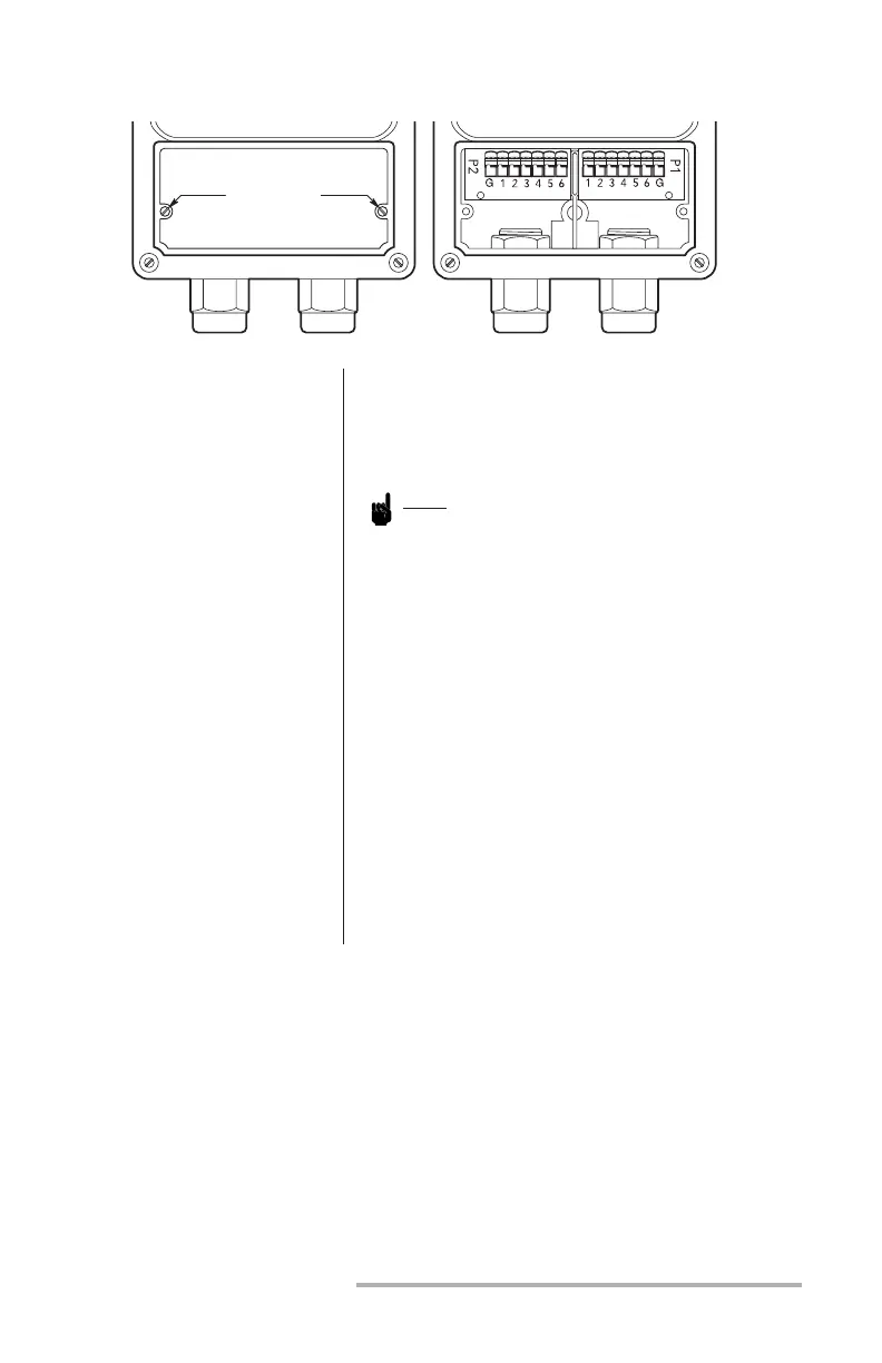
Figure 2 Coverplate & Terminal Connections
Remove these
two screws to
expose terminal
connections at right