Eclipse Rotary Actuator Instruction Manual 904-7/24/06
15
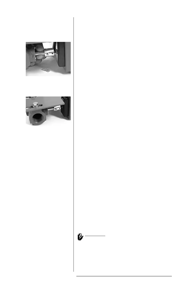
then the bracket must be re-aligned as follows:
a. Partially reinsert the M4 bolt
through the coupling.
b. Loosen the M6 and M8 bolts as
required to make small adjustments
to the bracket alignment until the
BV shaft can be turned by nger
within the coupling when the M4
bolt is removed.
c. Finger-tighten the bolts and repeat
step 8.
9. Tighten the M8 bolts to 5 Nm (45 lb-in) and
check if the alignment has shifted as in step
8. Tighten the M6 bolt to 2 Nm (19 lb-in).
Insert and tighten the M4 bolt to 1 Nm (9
lb-in).
10. Make the electrical connections either
temporary or as required by the application
and apply power. Verify for proper and
smooth motion over the full stroke range,
see step 2-d. Correct any abnormalities
before placing the equipment into operation.
Place the PRA into the correct operating
mode (manual or automatic) as required
by the application, Section 3 “Parameter
Selection” and “Manual Position Select” or
“Automatic Signal Input Select.”
8.
9.
Access is through the two electrical connectors at the
end of the actuator. Remove the front coverplate to
access the terminal strips, as shown in Figure 2.
Warning:
Risk of electric shock. Removal of the
cover plate allows access to conductors
carrying hazardous voltages.
aCtuator wiring