Eclipse Rotary Actuator Instruction Manual 904-7/24/06
11
aCtuator
mounting
Depending on your application, please keep the
following in mind when mounting the actuator:
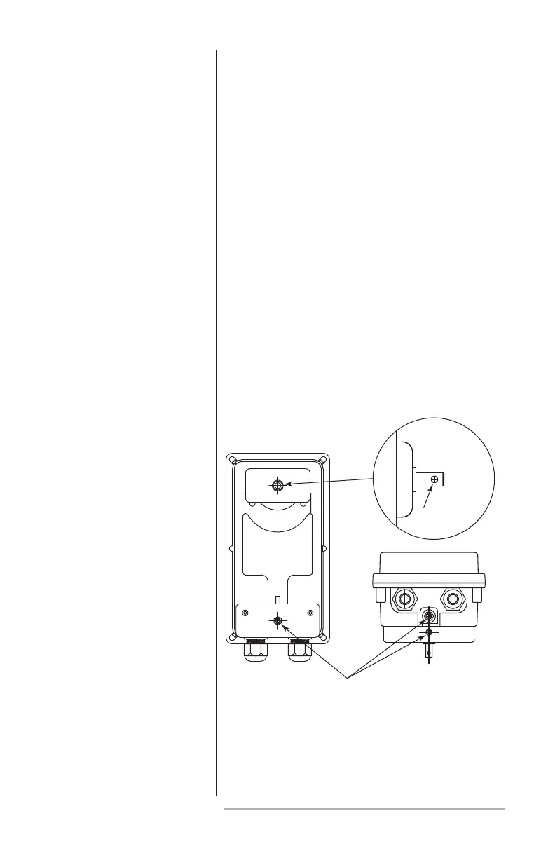
• The actuator housing has three mounting holes,
as shown in Figure 1. The holes are threaded and
use M6 metric screws.
• Mounting this actuator depends on the applica-
tion; See Data 904 and contact Eclipse, Inc. for
available mounting kits.
• When mounting the actuator, be certain that the
actuator’s drive shaft is properly aligned with the
other shaft to which it will be coupled to avoid
undue lateral stress.
• The actuator’s drive shaft has a 3mm through
hole for a coupler, as shown in Figure 1.
• Provide support for the weight of conduit or
cables into the actuator.
Figure 1 Coupler & Mounting Holes Location
Bottom End View
Mounting
Holes
Shaft Detail
3mm
(0.12”) Dia.