Eclipse Rotary Actuator Instruction Manual 904-7/24/06
18
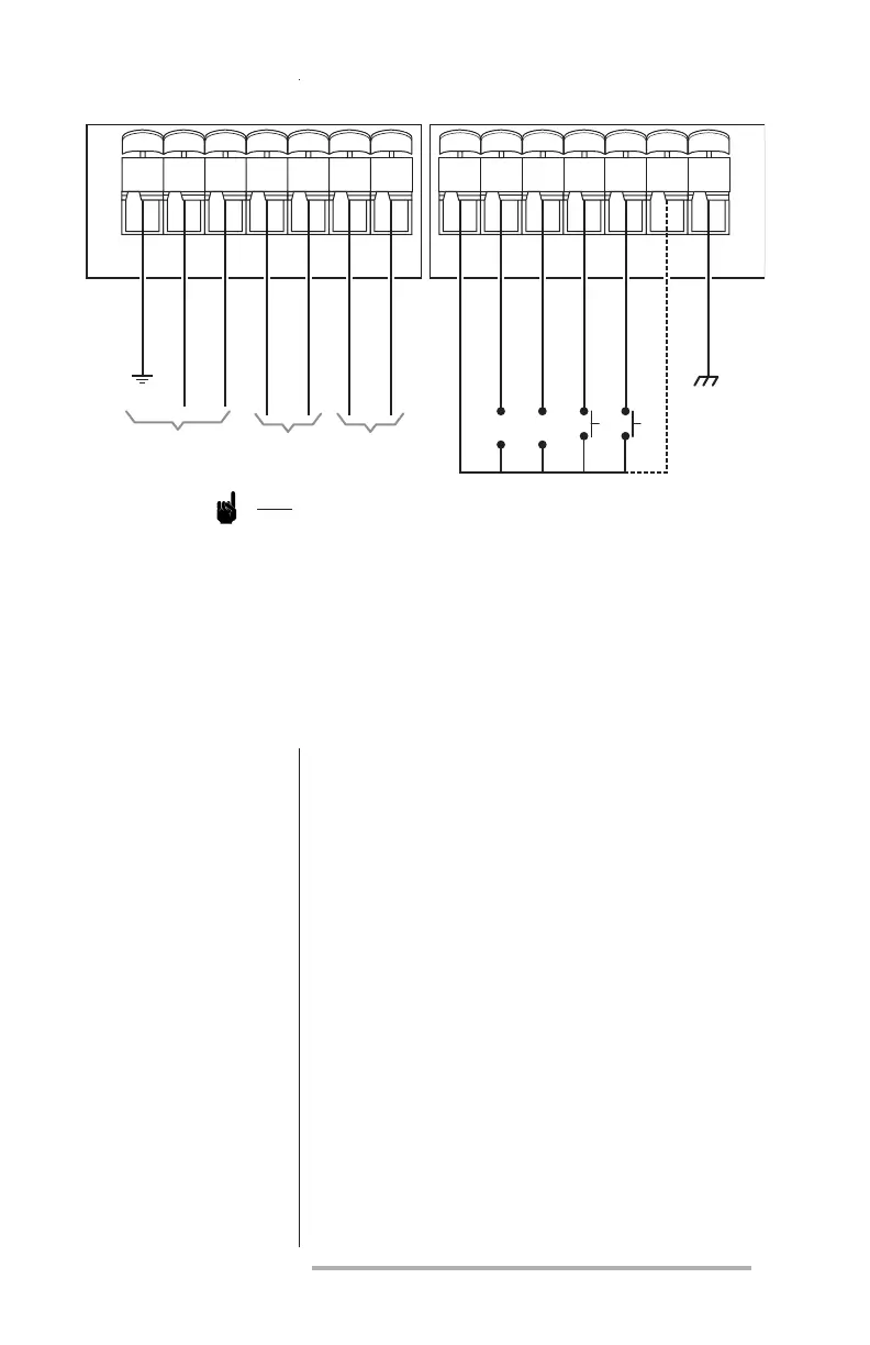
Note:
1. Separate low voltage signal wiring from high voltage signal wiring.
2. Control circuit wires must:
a) meet 90°C (194°F) specication minimum;
b) recommended range from 22 to 16 AWG (.5 to 1.5mm
2
), and
c) be in accordance with all applicable codes.
3. Insert only one wire per terminal.
4. Provide power supply circuit protection.
5. P2-G and P1-G are internally connected
Figure 3 Wiring Diagram for Actuator
Com (-)
Input
Contact Outputs
120 or 230 VAC
Power Supply
HF LF
+
–
+
–
4-20mA
0-10V
High Fire
Low Fire
LC
Shield
P1
P2
Earth
Neutral
Line
HF Com
HF Switch
LF Com
LF Switch
G 1 2 3 4 5 6 1 2 3 4 5 6 G